Key Requirements and Configuration Checks
- Start from the installed machine, including a non-HQD original spindle.
- Compare mounting references and tool position, not overall length alone.
- Classify each difference and agree acceptance before purchase.
Match the proposed configuration to its applicable drawing, operating data and machine requirements. Resolve mounting dimensions, auxiliary services and operating limits before accepting a spindle for the intended installation.
| Decision | Useful evidence |
|---|---|
| Existing installation | Nameplate, drawings, measured mount and connection photographs |
| Proposed replacement | Exact configuration, working data and required machine changes |
| Acceptance | Document identity, fit, services, commissioning and process record |
Identify the installed spindle before looking for a replacement
This process applies whether the existing spindle is HQD or another brand. Start with the unit installed on the machine and the machine's technical records. Photograph the complete nameplate so the model, voltage, current, speed and frequency remain readable. Include serial or revision identification where present. Keep the motor plate separate from labels on a fan, drive or other supporting equipment.
Describe why the replacement is needed. A failed unit, discontinued component, tooling change and production upgrade are different situations. Retain any fault record and service findings. If the underlying cause is unresolved, replacing the spindle may leave the same installation problem in place. The supplier needs the original identity and the desired outcome, while the machine builder needs the evidence behind the proposed change.
Before removing the installed spindle, retain its mounting drawing, connection details and previous commissioning records. Photograph the bracket, spindle nose, rear connectors and hose routing in their installed positions. Record the mounting datum used to establish tool reach so the replacement can be compared against the same reference. Measurements and disconnection must follow the machine's isolation procedure and be carried out by qualified personnel. Confirm unclear dimensions or electrical markings against the supplied assembly documentation before approving a replacement configuration.
Keep unknown fields explicitly empty in the comparison record rather than filling them from a similar photograph. Where labels and machine documents disagree, retain both and ask the relevant manufacturer or integrator to resolve the installed configuration. A complete starting record reduces the risk of ordering an assembly that matches the search phrase but differs from the machine.
Collect an evidence pack a supplier can actually compare
Photographs are most useful when each one answers a specific question. A front view identifies the nose and tooling arrangement; a side view shows support and projection; a rear view shows connectors and hose routes. Include a scale or measured drawing where a dimension governs fit. Avoid using perspective photos as the only evidence for a hole pattern or support diameter.
| Evidence | Required detail | Decision it supports |
|---|---|---|
| Nameplate | Full readable plate and unit identity | Electrical and operating comparison |
| Mount | Support region, bracket and fixing pattern | Mechanical candidate screening |
| Nose and tooling | Holder or ER family, nut and retention parts | Tool inventory and exchange compatibility |
| Rear services | Connector identity, function and routing | Electrical, cooling and auxiliary changes |
| Installed position | Mount reference, nose and working envelope | Reach and collision review |
| Machine documents | Drive, control, cooling and acceptance records | Integration and commissioning plan |
Name the files clearly and link each measurement to its location on the drawing. An annotated bracket sketch can distinguish an overall diameter from a permitted clamp region. When a supplier asks for another view, add it to the same record so the current specification does not become scattered across messages.
Include the parts you intend to reuse. A retained bracket, drive, holder set or water circuit creates a constraint, not an assumed match. List those components with their own identity and condition. The candidate comparison can then identify which constraints are met and which require an engineering change.
Measure the support and fixing arrangement
For a cylindrical mount, establish the actual support diameter and usable clamp region from the original drawing and machine installation. Compare those with the candidate's permitted region, not just a nominal body dimension. A housing can include steps, slots or areas unsuitable for support. The machine builder should determine the bracket design and tightening method from the supplied requirements.
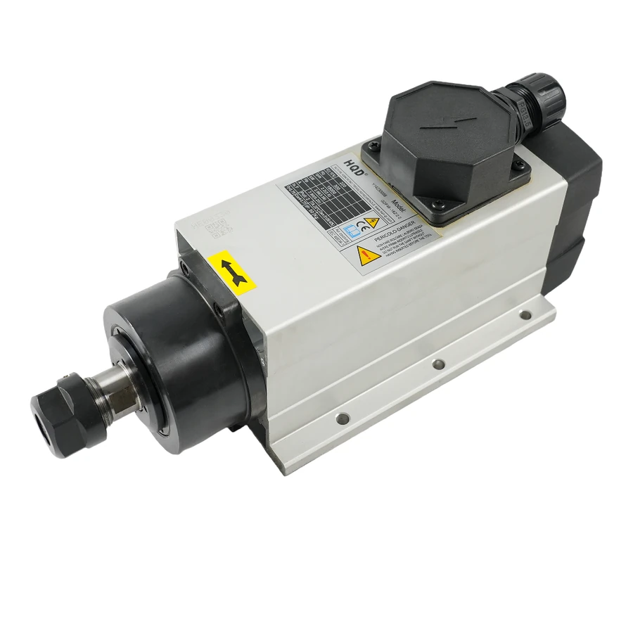
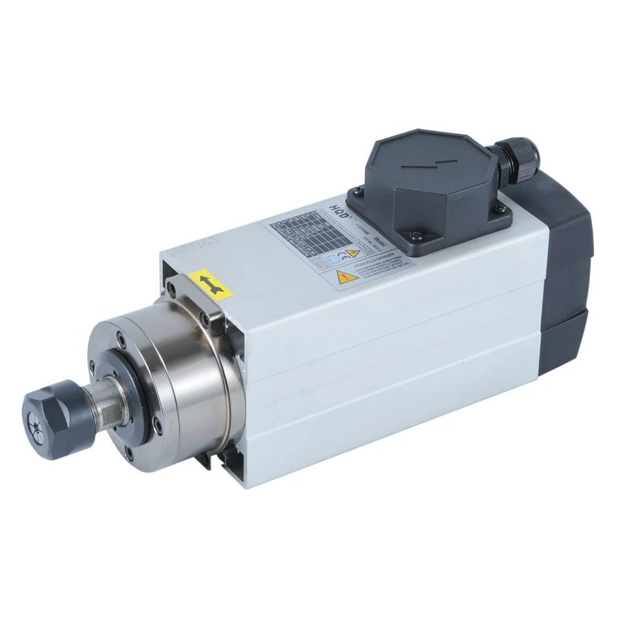
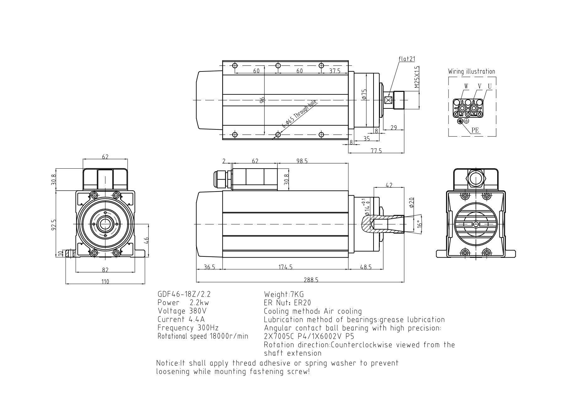
For base or housing mounting, record the fixing pattern, reference surfaces, fastener arrangement and orientation. GDF46-18Z/2.2 is an important HQD example: base-mount and housing-mount versions carry the same printed model but use different structures. A code-only inquiry does not resolve that choice. Include the exact physical variant and matching drawing in the replacement proposal.
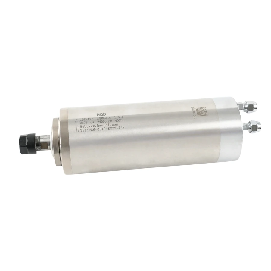
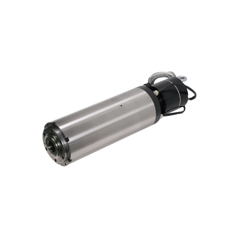
Compare the mass of the complete moving assembly with the Z-axis design. Include the bracket, tool assembly and moving services as well as the spindle. GDZ-17B is documented at 5 kg and GDL120 BT30 at 25 kg; these spindle values do not account for every item added to the axis. Assess the complete proposed installation before accepting a support change or power upgrade.
Compare the mounting reference to the tool tip
Record the distance from an agreed mounting reference to the spindle nose, then to the assembled tool tip. Keep the tool assembly and projection identified. This gives the machine builder a meaningful comparison of working position. Overall motor length includes rear structures and is not, by itself, the change in tool reach.
Review the full machine travel and the tool-change positions where applicable. A longer rear assembly can interfere with an enclosure even if the cutting end reaches the workpiece. Hoses, plugs and cable bends require space beyond the body drawing. A dust shoe or rack can create another constraint that does not appear in a bench photograph.
Mark changed reference distances on an overlay or dimensioned sketch. If a new bracket relocates the spindle, include the bracket change in the same review. Tool offsets and machine limits must be established through the integrator's setup process; they should not be inferred by subtracting two overall catalog lengths.
For a hypothetical 80 mm manual-spindle replacement, compare GDZ-17B and GDZ-23 using their exact drawings. They differ in ER interface, output and assembly dimensions despite sharing an 80 mm body. A diameter match makes them candidates for investigation, not a conclusion that the same bracket and offsets can be retained.
Compare the complete tooling inventory
For manual ER tooling, record the spindle interface, nut, compatible collets and actual cutter shanks. Distinguish cutting diameter from shank diameter, and keep metric and inch sizes separate. Existing collets should be evaluated for the exact intended assembly and condition. The ER tooling guide explains family and individual-size choices.
For ATC, record the taper, holder, retention component, gauge reference and tool-handling arrangement. A shared BT30 or ISO20 name is not the whole installation. Review retention geometry and rack interaction using the supplied documents. Include long or large assembled tools in the clearance review because the smallest holder may not represent the governing case. Third-party retention-part identification guidance supports this comparison, but does not establish a match to the supplied spindle or authorize reuse of another holder's tightening requirements.
A move from manual ER tooling to ATC changes more than the nose. It introduces holder storage, release controls, sensors and tool measurement. Treat that proposal as a machine conversion with its own engineering and acceptance plan. The ATC requirements guide separates those functions from the spindle purchase.
If the replacement is intended to solve a tooling limitation, state the actual shank and assembled tool requirement. For example, changing from ER11 to ER16 can address a different tool inventory, but the required operating point and machine fit still need review. Do not substitute a generic larger-collet description for an identified tool list.
Compare winding, frequency and drive output
Read the existing motor winding and selected candidate winding separately from the building supply. Keep voltage and current paired with the exact configuration. HQD GDZ-17B provides documented 220 V/6 A and 380 V/3.5 A alternatives, while GDL120 provides 220 V/19 A and 380 V/11 A alternatives. The selected pair belongs in the order and drive review.
Equal RPM does not guarantee equal electrical frequency. GDZ-23 is rated at 24,000 rpm and 400 Hz; GDL120 is rated at 24,000 rpm and 800 Hz. A drive retained from one installation must be evaluated for the other's complete output and control requirements. The kW printed on a drive is only part of that comparison.
For range models, use the original operating curve and its conditions. GDK100 voltage endpoints are curve values across frequency and speed, not two independent winding choices. Keep rated and maximum speed distinct as well. The VFD matching guide provides a structured electrical comparison without prescribing a particular drive's menu settings.
Retain the existing drive identity, ratings and configuration record before changes. Have qualified personnel establish the candidate-specific commissioning settings and supporting electrical design. An old parameter file is useful evidence of the previous installation; it is not an automatic setup for the new spindle.
Compare cooling and auxiliary connections by function
Identify every service used by the installed spindle: motor power, cooling, fan supply, sensors, feedback and any pneumatic release. Document connector or port function from the original machine information. Similar connector shapes do not establish identical pin functions, voltages or supplied hardware.
Air-to-water or water-to-air changes introduce supporting-equipment decisions. Compare the selected spindle's cooling requirements with the existing circuit or airflow path. Include rear connections, service access and moving-hose routes. The cooling comparison describes the installation record and routine checks.
For GDL40.5, the 24 V DC fan and sensor auxiliaries are separate from its 220 V motor winding. Other ATC configurations may have different included sensing or feedback. A reserved encoder connection does not establish that an encoder is installed; GDL110's catalog explicitly records no fitted encoder. Identify actual hardware before assigning control functions.
Where services change, mark who supplies and integrates each item. Retained equipment still needs a match to the new requirements. Newly introduced cooling, release or sensor equipment should have its own documentation and acceptance evidence, rather than being treated as a small accessory omitted from the replacement scope.
Make every difference visible before placing the order
Use one table for the original installation and the proposed candidate. Enter the evidence, consequence and responsible action for each mismatch. A difference can be acceptable when the machine builder designs and accepts the change. It should remain visible until that action is completed.
| Item | Existing evidence | Candidate evidence | Disposition |
|---|---|---|---|
| Mount and support | Original drawing and measured bracket | Exact HQD variant drawing | Retain, redesign or exclude |
| Tool reference | Installed nose and tool assembly | Candidate nose and holder assembly | Review reach, limits and measurement |
| Drive | Existing motor and drive records | Chosen winding and working data | Retain after review or change |
| Services | Installed circuits and hardware | Required cooling, auxiliaries and release | Identify equipment and integration |
| Production requirement | Accepted tool and process record | Required candidate working point | Agree representative evaluation |
Use four clear outcomes: matched with evidence, change designed, evidence missing, or candidate excluded. A missing dimension is not a failed match, but it is also not approval to proceed. Request the exact information and leave that field open until the supplied configuration resolves it.
This format is useful when several quotations arrive with similar model names. Compare their complete configuration and included scope against the same original record. It prevents a cheaper or faster alternative from silently changing the bracket, winding or tooling assumptions behind the project.
Agree staged acceptance for the installed system
Start with delivered identity and documentation: full model, physical structure, chosen winding and the supplied drawings. Compare the delivered assembly against the agreed order before installation. Record any discrepancy and resolve it with the supplier; do not modify the installation around an undocumented substitution.
Mechanical fit and services form the next stage. The integrator should verify the mount, clearances, tool reference, cooling and electrical arrangements against the accepted design. Keep document checks separate from commissioning. A correct label does not establish that the machine was wired or supported according to its requirements.
Commissioning follows the spindle, drive, tooling and machine instructions with qualified personnel. Record the permitted operating checks and protective responses defined by that plan. For ATC, include holder handling, state detection and tool measurement. Finally evaluate the agreed representative process, retaining the tool, operating point and acceptance criteria.
| Stage | Evidence to retain | What it establishes |
|---|---|---|
| Delivery | Identity and supplied documents | The ordered configuration arrived |
| Installation | Fit, clearance and service records | The assembly follows the agreed design |
| Commissioning | Operating and protective-function results | The integrated system passed its defined checks |
| Process | Tool, conditions and workpiece result | The agreed application was evaluated |
Compare quotations against the same replacement scope
Give each supplier the same original evidence and list of retained components. Ask each proposal to identify the exact spindle structure, winding, supplied tooling and documentation. Keep any proposed alternative in a separate comparison row so its installation changes can be evaluated before the order is accepted.
Include the supporting work needed for a difference: bracket design, changed cooling equipment, drive review or an ATC conversion. A quotation for the motor does not automatically include those services. Name the responsible party and required acceptance evidence for each change. This lets the buyer compare complete proposals instead of prices attached to different assumptions.
Before ordering, summarize the accepted configuration and open items in one record. The supplier can resolve component questions while the integrator resolves machine changes. Preserve the final quotation scope with the installed documents so later service can identify which parts and work belonged to the replacement project.
Leave a useful record for the next replacement
Keep the final difference table with the drawings, delivered identity, commissioning record and accepted process baseline. Include revised bracket or connection documents and the responsible service contact. The next technician should be able to distinguish the original machine design from the changes made during this replacement.
For an inquiry, send the old nameplate, mount and nose evidence first, then the retained drive, services and tooling. State whether the project is a like-for-like investigation or an upgrade and identify acceptable machine changes. Include quantity and destination with the shortlisted HQD codes and physical variants.
GDF46 Base Mount and Housing Mount assemblies require different fixing arrangements even when the printed model code is the same. For a manual ER16 replacement, compare the permitted clamp region, nose position and motor data against the existing installation. A BT30 ATC conversion also requires compatible holders, retention hardware, release services, sensing and controller interlocks. Confirm the exact mounting variant, selected winding and retained machine equipment in the quotation request, and resolve every interface change before approving the order.