Key Requirements and Configuration Checks
- Treat holders, rack, release, sensing and measurement as one project.
- A manual-router retrofit needs an explicit machine-change review.
- Define observable exchange states and staged acceptance with the integrator.
Match the proposed configuration to its applicable drawing, operating data and machine requirements. Resolve mounting dimensions, auxiliary services and operating limits before accepting a spindle for the intended installation.
| Decision | Useful evidence |
|---|---|
| New machine | Tool sequence, holders, axis envelope and integration responsibilities |
| Retrofit | Retained machine systems and an itemized change assessment |
| Acceptance | Mechanical fit, services, state handling and tool-length records |
Choose the new-machine or retrofit planning path
For a new machine, define the tool sequence, holder inventory and exchange method early enough to influence the mechanical and control design. Spindle, rack, axis travel, guarding, services and tool measurement need a shared installation plan. A motor selected after those spaces and interfaces are fixed may create avoidable redesign work.
For a manual-router retrofit, begin with the existing machine and the reason for adding automatic exchange. Record the current mount, Z-axis assembly, drive, controller, working envelope and tool-measurement method. Identify which systems must remain. The machine builder or qualified integrator should assess whether the proposed conversion can meet the required functions and acceptance, rather than treating ATC as a motor-only replacement.
The two paths share component checks but differ in constraints. A new design can reserve rack space and define interfaces around the selected assembly. A retrofit must compare the existing design with each change. Use the replacement checklist for the original evidence, and retain a separate ATC integration record for the added functions.
State the production objective concretely. Count recurring tools and exchanges in a representative job, and record setup and measurement activity. This gives the integrator a workflow to evaluate. It does not justify an assumed percentage improvement in throughput or establish that a larger spindle is necessary for automatic exchange.
Identify the complete holder and retention arrangement
Begin with the spindle-to-holder interface, then the cutter clamp inside the holder. ISO20, ISO30 and BT30 are different taper families; an ER collet chuck may be part of a holder without describing its spindle connection. Record the exact assembled holder, retention component, gauge reference and intended cutter projection.
Keep individual tool assemblies identified. A small engraving tool and a larger machining tool may create different handling envelopes even when their holders share a taper. Use the longest and largest intended assemblies when reviewing clearances and rack spacing. Count spare and replacement holders where the production plan requires them, rather than counting only cutting tools.
Compare retention components against the machine and supplied spindle requirements using their exact drawings and identities. A matching taper name does not establish the required retention geometry, thread or release arrangement. Keep third-party retention-part numbers and tightening guidance linked to the equipment they describe; apply them to an HQD assembly only where the applicable supplied-unit documentation establishes the match.
The selected ISO20, ISO30 or BT30 interface, holder and retention components must be specified together with their machine interfaces. Compare the holder gauge reference, retention geometry and handling arrangement against the spindle and rack documents. Keep the accepted holder and retention drawings with the spindle order so tooling is purchased against the same installation requirements.
Review mounting, mass and complete travel
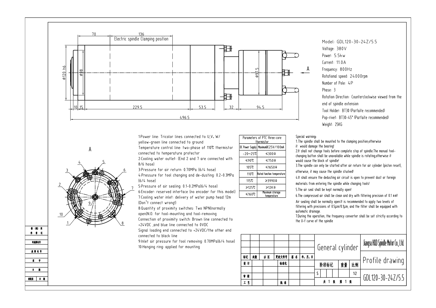
Compare the permitted support region, fixing arrangement, orientation and reference dimensions with the machine structure. Body diameter alone does not define the mount. GDL120 has a 120 mm body, 136 mm clamp length and 496.5 mm overall length; GDL80 has an 80 mm body and 98 mm clamp length. Keep every dimension with the exact configuration.
Have the machine builder review the complete moving mass, including bracket, holder, tool and moving services. GDL120 is documented at 25 kg, while GDL40.5 is 8.9 kg and has a side auxiliary assembly. These values inform different support and clearance discussions; they do not establish a universal axis capacity or an interchangeable installation.
Review the complete assembly at cutting, travel and tool-exchange positions. Allow for rear connections, hose bends, fan or release structures, the rack, dust extraction and service access. Include connections and accessories in the layout even when they extend beyond the spindle-body outline, and check their clearances throughout the intended machine movements.
Design the rack or changer around real tool assemblies
Record the exchange method and holder-handling geometry with the machine builder. Identify the rack positions, access direction, spacing and movement required to store and retrieve each assembly. Compare those requirements with the available axis travel and working envelope. A rack location that reduces usable table area should remain visible in the project proposal.
Include the largest tool diameter, longest projection and any other geometry that governs clearance. Review neighboring positions as well as the position being used. Plan protection from chips and dust with the machine's extraction and enclosure design. Do not presume that a generic rack with the same taper label will handle every assembled tool used in the job.
Document position references and the method used to establish them during setup. Mechanical adjustment and controller values need a consistent accepted record. A rack position copied from another machine is not evidence for the current installation, and a successful exchange of one empty holder does not evaluate the full intended inventory.
For a retrofit, identify whether the rack, added movement and services require modifications to the existing frame or enclosure. Include those changes and lost working space in the acceptance discussion. This helps the buyer compare a conversion with a new-machine proposal using practical installation consequences rather than a motor price alone.
Match the winding, working point and drive
Record the chosen motor winding and its current, alongside the required working speed and duty. GDL120 offers 220 V/19 A and 380 V/11 A configurations at 24,000 rpm and 800 Hz. The building supply and drive input must be recorded separately from motor output. A matching power label does not establish the drive's complete suitability.
Compare electrical frequency explicitly. GDL40.5 has an 18,000 rpm rated point at 300 Hz and a 24,000 rpm maximum at 400 Hz. GDL80 is rated at 24,000 rpm and 800 Hz; GDL110 is rated at 18,000 rpm and 600 Hz. Shared ATC tooling does not make their drive requirements the same.
| HQD ATC example | Tooling and cooling | Documented point | Installation distinction |
|---|---|---|---|
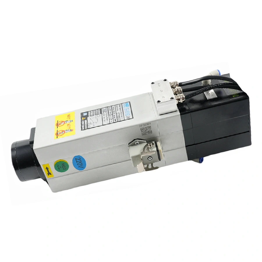
| GDL40.5 | ISO20; air | 2.2 kW; 18,000 rpm/300 Hz rated | 372.5 mm overall; side auxiliaries; 8.9 kg |
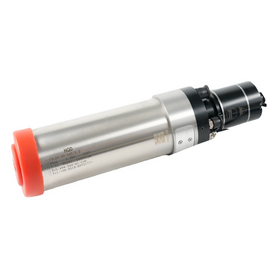
| GDL80-20-24Z/2.2B | ISO20; water | 2.2 kW; 24,000 rpm/800 Hz rated | 80 mm body; 98 mm clamp; 335 mm overall |
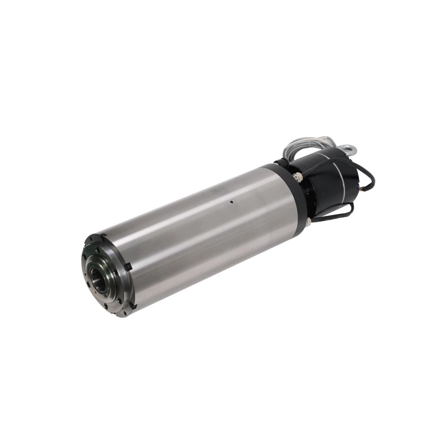
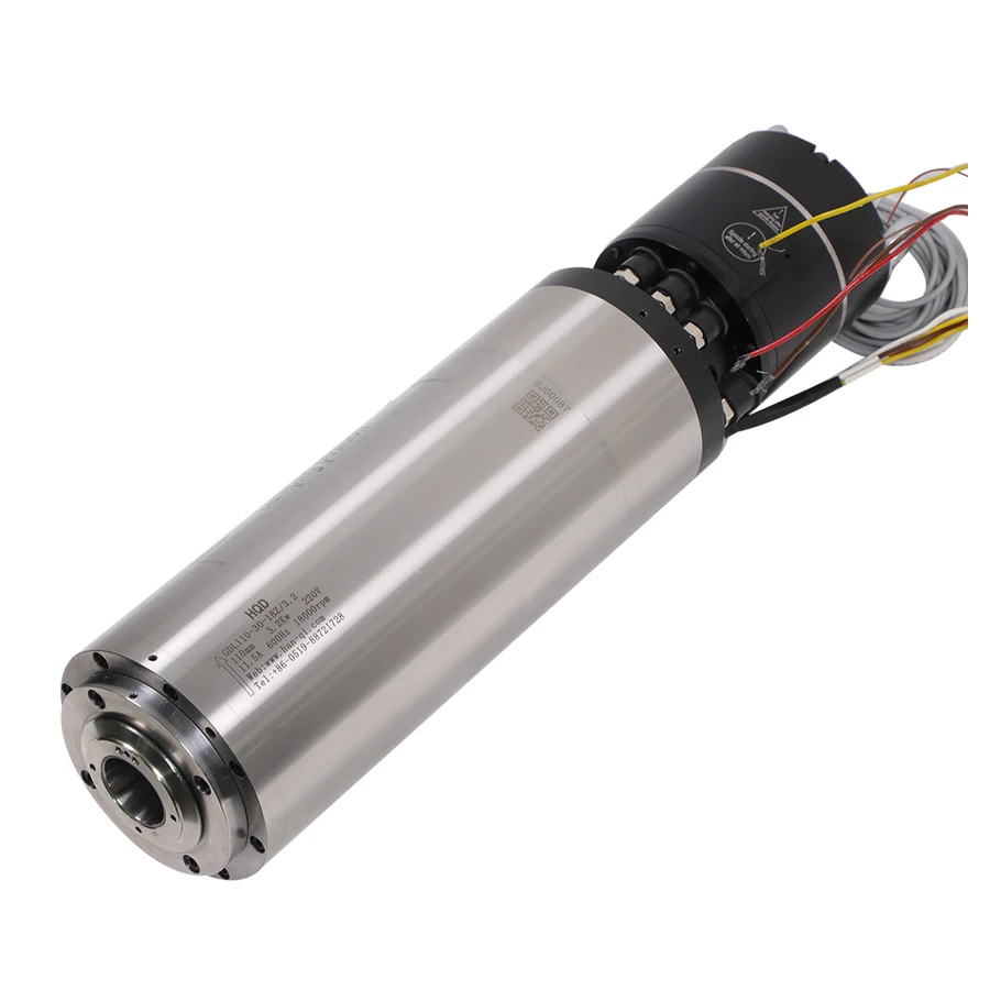
| GDL110-30-18Z/3.2 | BT30; water | 3.2 kW; 18,000 rpm/600 Hz rated | 110 mm body; 132 mm clamp; no fitted encoder |
| GDL120-30-24Z/5.5 | BT30; water | 5.5 kW; 24,000 rpm/800 Hz rated | 120 mm body; 136 mm clamp; 25 kg |
The drive specification must match the selected winding, current, frequency and intended operating point. Retain the complete electrical record with the supplied motor requirements and the exact drive manual. The integrator should establish the configuration for that spindle-drive pair; settings accepted for another ATC assembly require a separate review before reuse.
Specify cooling, release air and auxiliary supplies
Identify motor cooling separately from pneumatic release and cutting-zone services. An air-cooled ATC spindle still needs the supplied release arrangement and control functions. A water-cooled one needs both its liquid circuit and the applicable pneumatic/control installation. Cooling type does not establish release pressure, port function or sensor logic.
Obtain the pneumatic requirements for the supplied assembly, including port functions, required pressure and flow conditions, air preparation and release information. Have the integrator specify the equipment and monitoring needed to maintain those conditions at the machine. Record the applicable assembly instructions with the design rather than transferring pneumatic values between GDL models.
GDL40.5's 24 V DC fan and sensor supplies are separate from its 220 V spindle winding. Include each auxiliary supply and function in the electrical drawing. Document how cooling equipment and release services interact with the machine's operation and protective responses. Connector appearance or a neighboring model's wiring is insufficient evidence.
Route all services through the complete travel and exchange movements. Provide appropriate support, protection and access according to the machine design. Identify who supplies hoses, cables, valves and control interfaces in the project scope. A quotation for the motor alone should not be interpreted as a complete ATC package.
Define the exchange states and their required evidence
The machine integrator should define the tool-change sequence around observable states and the supplied sensor functions. Establish how stopped rotation, holder clamp or release, and an incomplete exchange are identified. For each state, record the available signal, the condition it represents and the required machine response. The sequence must be designed and validated for the actual controller and installed hardware.
Separate a command from evidence that the commanded state occurred. Sending a release request does not alone prove a holder is released, and a completed movement does not prove a tool is retained correctly. Identify the signals and hardware actually available on the supplied spindle and machine, then define the response to missing or contradictory information.
| Planning state | Evidence/function to establish | Integration question |
|---|---|---|
| Ready to exchange | Required stopped/position/service conditions | What permits the sequence to start? |
| Release requested | Supplied release arrangement and state information | How is the requested state observed? |
| Holder handled | Rack/changer and motion condition | What establishes successful handling? |
| Holder clamped | Applicable retained-tool evidence | What permits the next machine operation? |
| Incomplete exchange | Defined fault or unexpected-state information | What response and recovery procedure applies? |
Use the table to review the control design with the integrator. The exact implementation depends on the supplied hardware, controller and machine requirements. A reserved connector is not proof that a sensor or encoder is fitted. In particular, GDL110's catalog records no installed encoder, so a feedback-dependent function needs its own hardware review.
Plan tool lengths, references and inventory records
Automatic exchange does not automatically establish tool length. Define how each assembled tool is measured, how its identity maps to the controller record, and how that record is updated after a cutter or holder changes. Use the machine's appropriate measurement equipment and setup process rather than assuming that a rack position establishes the cutting tip.
Keep the mounting reference, holder gauge reference and actual cutter projection distinct. Their relationship matters for reach, clearance and tool offsets. A spindle's overall length is not a tool-length setting. Retain the accepted setup record and identify which physical or tooling changes trigger measurement or review.
Include damaged, replaced or reassembled tooling in the inventory process. A cutter changed inside the same holder can alter projection, while a substituted holder can change the assembly reference. The operating team needs a clear procedure under the machine documentation so stored controller values continue to describe the actual tools.
For project acceptance, define how intended tool assemblies will be identified and measured, then evaluated in representative exchanges and processes. An empty-holder demonstration alone does not establish the required tool-length workflow. Keep measurement results with the inventory and commissioning record so later setup has a known baseline.
Make the manual-router changes explicit
A retrofit assessment should list each retained component and the evidence supporting its reuse. Begin with the machine controller and required exchange functions, then the axis/mount, drive, rack space, services and measurement. A manual spindle removal creates space for another assembly, but it does not demonstrate that all added ATC functions can be implemented.
| Retrofit item | Existing evidence | Possible project consequence |
|---|---|---|
| Controller and interfaces | Exact model, functions and machine documentation | Added interface or control redesign |
| Axis and mounting | Support design, travel, mass and clearance | Bracket or mechanical change |
| Drive | Full input/output rating and configuration | Motor-specific review or drive change |
| Rack and workspace | Planned holder assemblies and exchange travel | Added hardware or reduced working area |
| Cooling and pneumatics | Existing equipment and applicable conditions | New circuits and monitoring |
| Tool measurement | Current method and controller records | Added equipment or revised workflow |
Classify each item as supported with evidence, requiring an accepted design change, or unresolved. The result is a conversion scope with responsibilities and acceptance criteria. It allows the buyer to compare the complete project with a new machine or a retained manual workflow, without promising a capability from the spindle alone.
For a proposed cabinet-router conversion using several assembled tools, assess repeated manual setup alongside the space and services needed for a rack, controller sequence and tool measurement. Record the recurring job, existing machine constraints and required changes before choosing the ATC configuration. Any expected production improvement needs evaluation against that workflow; it cannot be established from the spindle specification alone.
Verify the installation in stages
Agree acceptance before purchase and installation. Begin with delivered spindle, holder and supporting-equipment identity, then compare the supplied documents with the accepted design. Mechanical checks should include support, clearance, rack handling and service routing. Qualified commissioning follows the equipment and machine instructions and the integrator's plan.
The integrator's validation procedure should establish the defined state handling and protective responses for the installed control system. Record the agreed functions, the evidence used to verify them and the response to an incomplete exchange. Any validation involving abnormal conditions must follow the machine's approved procedure and preserve its required protective functions.
Then evaluate the intended holder inventory, tool measurement and representative production process. Record the tool assembly, conditions and acceptance criteria. A successful exchange of one tool demonstrates one observed event; it does not replace the complete inventory, service and control review needed for the intended installation.
Keep document identity, mechanical installation, electrical/services commissioning, tool exchange and process evaluation as separate records. That makes a discrepancy actionable and avoids treating an acceptable workpiece as proof that every supporting function was validated.
Assign the supporting equipment and project responsibilities
Create a supply list covering the spindle, holders and retention components, rack or changer, drive, cooling equipment, pneumatic preparation and release hardware, auxiliaries, sensors and measurement equipment. Identify what is included, what is retained and what another party provides. Exact component identities matter when interfaces depend on them.
Assign mechanical design, electrical/control integration and commissioning to the appropriate project parties. The spindle supplier can provide component documents, while the machine integrator must define and accept the system built around them. Keep those responsibilities with the quotation so omitted work does not remain hidden until installation.
Use the same scope during handover. Retain component drawings and inventory together with the integrated machine records and acceptance results. Later changes to a holder, rack position, drive or measurement method can then be reviewed against a known installation rather than an isolated spindle purchase.
Build a complete ATC inquiry and project handover
Send the machine model and project path, intended job/tool sequence, selected taper and holders, spindle candidates and installation measurements. Include the chosen winding, drive details, cooling and available pneumatic/control services. Identify the integrator and the components that must remain for a retrofit. Add quantity and destination for the quotation.
Ask the supplier to identify the supplied-unit documents and included hardware, while the machine builder defines the supporting installation. Keep rack, valves, sensors, auxiliary supplies, measurement and commissioning responsibility in the scope. This prevents a motor-only quotation from becoming an ambiguous promise of a complete machine conversion.
Retain the final drawings, tooling inventory, control-function record and commissioning results with the machine. Identify the supplied spindle assembly and the accepted supporting equipment in the same handover record. The completed installation should have documented tool-exchange functions, measured tool references and acceptance evidence for the intended process, with unresolved requirements assigned before production release.