Key Requirements and Configuration Checks
- Copy the complete code and retain the source photo.
- Shared codes need a mounting, nose or speed description.
- Use applicable specifications rather than a universal decoding rule.
Match the proposed configuration to its applicable drawing, operating data and machine requirements. Resolve mounting dimensions, auxiliary services and operating limits before accepting a spindle for the intended installation.
| Printed code | Additional identity needed |
|---|---|
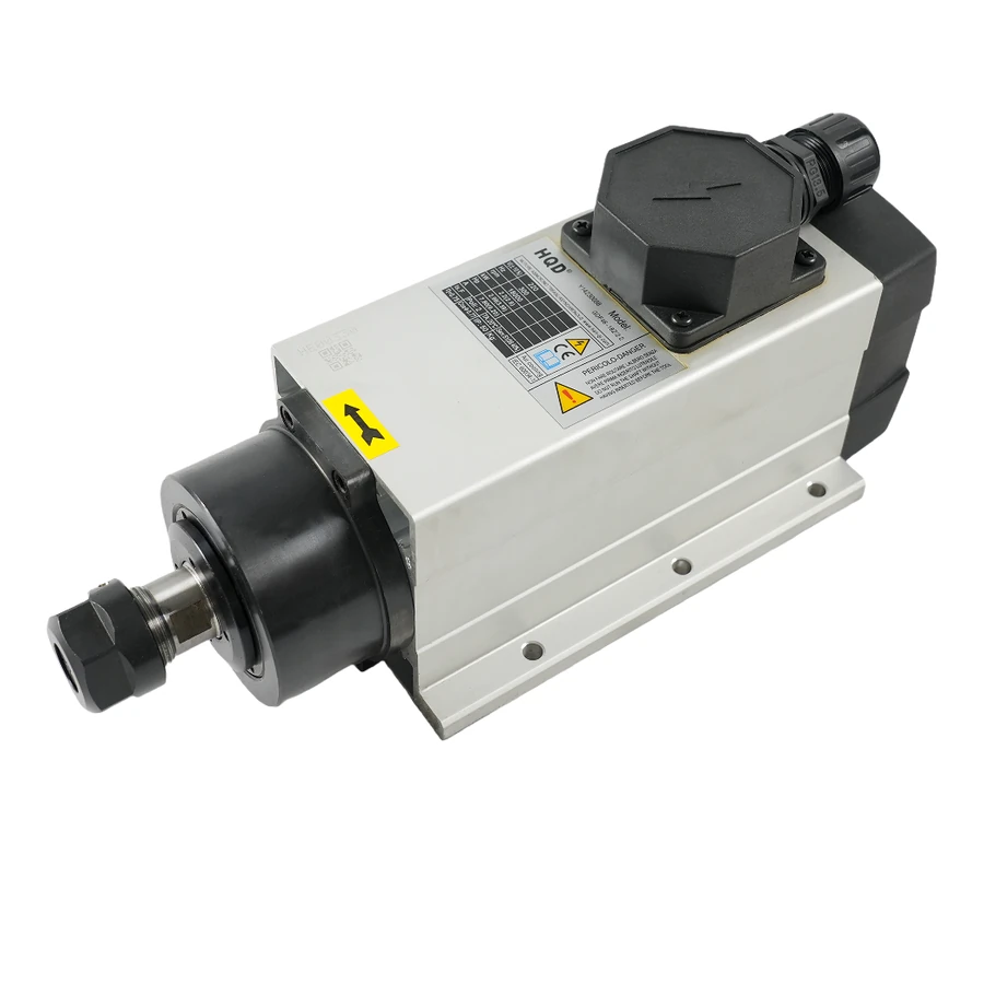
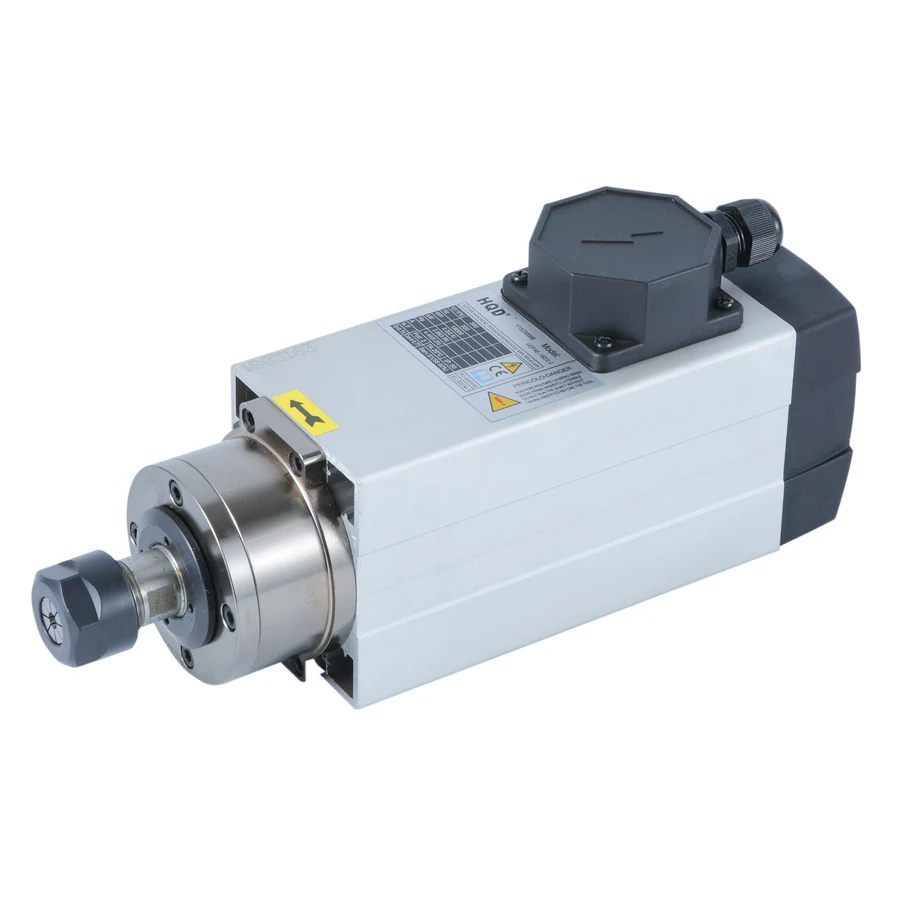
| GDF46-18Z/2.2 | Base Mount or Housing Mount |
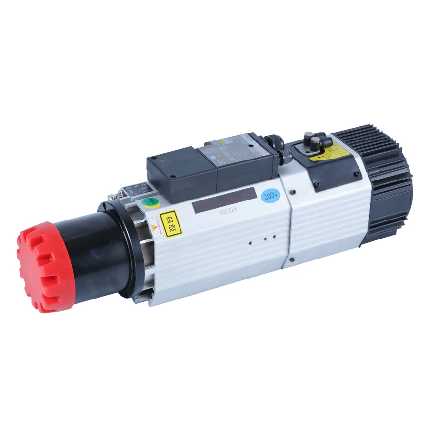
| GDL70-24Z/9.0 | ISO30 long-nose or short-nose configuration |
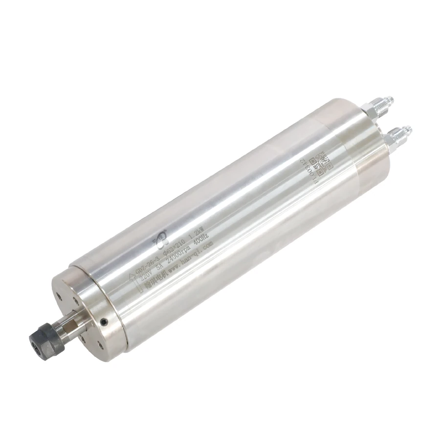
| GDZ-26-3 | Retain the 24,000 rpm / 400 Hz version |
Record the printed code before searching
Photograph the nameplate straight on so the full model, voltage, current, frequency and speed can be read. Keep a second photo showing where that plate sits on the assembly. Copy the printed model with its punctuation and suffix into the inquiry, alongside any separate configuration description. If a character is unclear, preserve the photo rather than silently replacing it with the closest catalog name.
The model code is a useful starting point, not the complete installation specification. A search can identify several candidates even when the printed string appears exact. Match the body, support and nose shown in the actual machine, then check the electrical and service data. The nameplate and applicable drawing answer different questions; retaining both prevents a family-level match from being mistaken for a complete supplied-unit identification.
Identify tool-change and cooling requirements across GDL, GDF, GDZ and GDK families
GDL configurations in the documented HQD examples use automatic tool change; GDF configurations combine manual tooling with air cooling, while GDZ and GDK examples combine manual tooling with water cooling. These family characteristics provide an initial filter for the machine's tool-change and cooling requirements, but do not establish every holder, winding, mount or connection within a series. Record the exact model and physical variant, then compare its supplied specifications with the intended tooling, available support, electrical output and service connections. Confirm unfamiliar or historical configurations from their own nameplate and applicable drawings.
A GDL name therefore starts an ATC integration discussion, while a GDF name makes fixing and airflow important. A GDZ comparison begins with body, nose and support dimensions; a GDK comparison should also retain the working curve and duty conditions. Keep those useful family distinctions without treating them as a manufacturer's universal decoding specification for every historical or future code.
Retain nose descriptions that the printed code does not resolve
GDL70-24Z/9.0 has separate ISO30 long-nose and short-nose configurations in the catalog. Retain the nose description in addition to the printed code. Compare the support reference, nose and holder position, complete assembly and rear services with the actual machine. A photograph can help distinguish the assembly, while the applicable outline is needed to locate it in the machine envelope.
Do not calculate a tool-tip offset solely from the difference in overall lengths. Overall space includes rear structures, and the installed tool position also depends on mounting reference, holder gauge arrangement and cutter projection. The GDL70 B-suffix model uses another configuration, so keep its full code as well. Confirm the taper and supplied retention arrangement instead of assuming that a shared numerical label identifies the same ATC system.
A suffix is significant without having one universal meaning
GDF80-24Z/2.2 uses ER16, while GDF80-24Z/2.2B uses ER20 and another assembly. GDZ-18 uses ER11; GDZ-18B uses ER16; GDZ-18-2 uses ER11B and a different rated point. These are concrete model differences worth retaining in a search, accessory request and quotation. They do not prove a rule that every B suffix means ER20, ER16 or automatic tool change.
Keep the complete tooling designation with the exact nose drawing. ER11B should not be shortened to ER11 when selecting parts, and an ER family is not one accepted shank diameter or every accessory thread. Verify the chosen collet's marked gripping range, nut and nose hardware. The specific model facts provide the useful interpretation; the suffix alone is insufficient evidence for an accessory or replacement conclusion.
Read power and speed from applicable specifications
GDK100-12-24Z/2.2-4.4 has a documented 12,000–24,000 rpm operating range and 2.2 kW rated output, while the original curve includes a separate higher output with duty conditions. Keep S1/S6-20% and TA20°C with the applicable curve information. The larger number in the code is not a reason to describe the unit as an unconditional 4.4 kW continuous spindle or to remove its working-point conditions.
GDL40.5-ISO20-24Z/2.2 illustrates another boundary: the catalog distinguishes an 18,000 rpm rated point and a 24,000 rpm maximum. Read those fields separately rather than letting the code's speed-like number overwrite the rated point. A curve, nameplate and supplied operating instructions are needed for the actual duty. The model code can lead to the evidence, but it cannot establish a working region by itself.
Include speed configuration where the code is shared
The documented 24,000 rpm GDZ-26-3 configuration has a 400 Hz operating point, 1.2 kW rated output and a 220 V / 5 A specification. Its original drawing also refers to another speed version, so the family code alone is insufficient for electrical identification. Retain the 24,000 rpm qualifier in the inquiry and document request, and compare the actual nameplate with the applicable drawing. Do not transfer those power, current or frequency values to a 36,000 rpm unit bearing the same family code; obtain that unit's own supplied specifications before reviewing the drive or tooling.
GDZ-27 and GDZ-27-2 list another explicit distinction: 24,000 rpm / 400 Hz versus 30,000 rpm / 500 Hz, despite shared headline body and length dimensions. Keep the complete code, actual nameplate and intended working speed together. A common 4.5 kW label or mechanical envelope does not establish identical VFD settings or approval of an existing cutter, collet and nut assembly at the different operating speed.
Keep conflicting markings visible until the supplied unit is identified
GDZ-26-1 has different current markings: its drawing lists 5 A and the nameplate photo shows 3.5 A. The drawing and specification table support 0.8 kW, while the photo labels power as 0.8 W. Retain those records and request an applicable supplied-unit nameplate and electrical specification. Do not choose the current by looking for the most similar 0.8 kW or ER11B model.
GDK100-24Z/3.2 has conflicting nose-thread annotations in its drawing, so accessory selection also needs the applicable supplied-unit information. A correct model search does not resolve every source discrepancy. State the unresolved issue in the inquiry and keep the relevant drawing or photo with it. This gives the supplier a specific configuration question to answer before drive sizing, accessory ordering or machine installation is finalized.
Turn a search result into a complete configuration request
Spaces, punctuation and common typing variations can help locate a model record, but do not identify a different physical version. Retain the standard printed model together with its mounting, nose or speed description once a candidate is found. Compare the candidate's assembly photographs and applicable installation drawing with the actual spindle, checking fixing references, nose geometry and rear connections. An approximate name match provides a candidate for investigation; replacement suitability still depends on the machine's mechanical interfaces, supplied winding, operating point, tooling and service requirements.
Send the full code and readable nameplate, fixing and nose photos, current mount dimensions, drive model and cooling or ATC services. Add the selected winding where choices are listed, quantity, destination country and postal code, and accessory or extra document needs. Leave unknown technical information blank rather than filling it from a nearby model. CINKR can use that record to discuss the exact configuration and confirm current availability by email.
Keep an identification record for the complete assembly
Create one record that joins the printed model to the physical installation. Record the source of each value: nameplate for the supplied motor identity, an applicable outline for fixing and clearance, and the electrical record for the intended winding and connections. Where two documents appear to describe different units, retain both with their labels instead of merging selected values into a new specification.
For a previously installed spindle, record the parts you intend to retain. That includes the mount, tooling, drive, cooling circuit and, for an ATC installation, the holder and release system. The model code can help locate a candidate, but these interfaces determine the comparison that follows. Include a photo of the complete assembly and clear views of its fixing and rear services so the evidence can distinguish a body variant from a similar-looking motor.
A useful identification record also notes what is still unresolved. If the winding is unreadable, say that the nameplate photo needs clarification. If the nose or support is hidden in the machine, identify the missing view or dimension. Do not fill those gaps from another configuration merely because its title is close. The purpose of the record is to make each known and unknown condition visible before a quotation or installation decision.
Move from an identified code to a configuration comparison
Once the code and assembly are recorded, compare the candidate's tooling, mounting references, winding and operating point with the machine. An exact code match is helpful, but it still needs the applicable configuration. A different code may be worth reviewing when the installation is changing, provided the physical and electrical differences are made explicit. Neither situation establishes interchangeability from the name alone.
Compare the configuration-specific outline, motor specification and connection documents with the machine requirements. For drive matching, verify the supplied winding voltage/current pair and required output frequency against the VFD's capabilities. For a retained-machine replacement, compare fixing references, nose position, tooling, cooling and rear-service clearance. An ATC candidate additionally requires a compatible holder, rack, retention arrangement, release services and state signals. After those technical conditions are recorded, list the requested accessories and documents, quantity and destination so the quotation identifies a complete proposed supply rather than an unresolved model name.
Keep the chosen code and configuration consistent across the inquiry, proposed item description and attached files. If the candidate changes during the discussion, update the record and check which documents still apply. This is particularly useful for shared GDF46 codes, GDL70 nose variants and a speed-qualified GDZ-26-3 request. It prevents an earlier drawing or winding choice from silently becoming the specification for a later candidate.