Key Requirements and Configuration Checks
- Compare complete installations, including airflow or water equipment.
- Keep motor cooling separate from cutting fluid and ATC release air.
- Use supplied-unit requirements to build a maintenance and fault record.
Match the proposed configuration to its applicable drawing, operating data and machine requirements. Resolve mounting dimensions, auxiliary services and operating limits before accepting a spindle for the intended installation.
| Decision | Useful evidence |
|---|---|
| Air-cooled installation | Fan arrangement, intake/exhaust path and auxiliary supply |
| Water-cooled installation | Circuit requirements, heat removal, routing and leak access |
| Operation | Baseline observations, environmental conditions and service records |
Compare the whole cooling installation
An air-cooled spindle transfers heat through an airflow arrangement, while a water-cooled spindle transfers heat into a liquid circuit that must reject it elsewhere. Neither label selects the tool interface, mounting or electrical working point. Start by comparing configurations that can meet the same machine requirement, then identify the services and maintenance each one introduces.
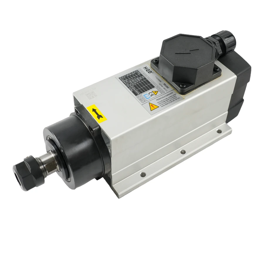
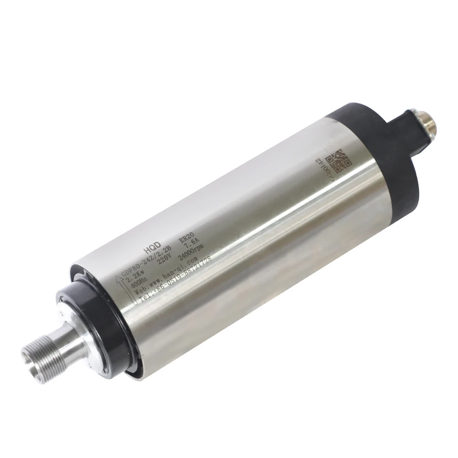
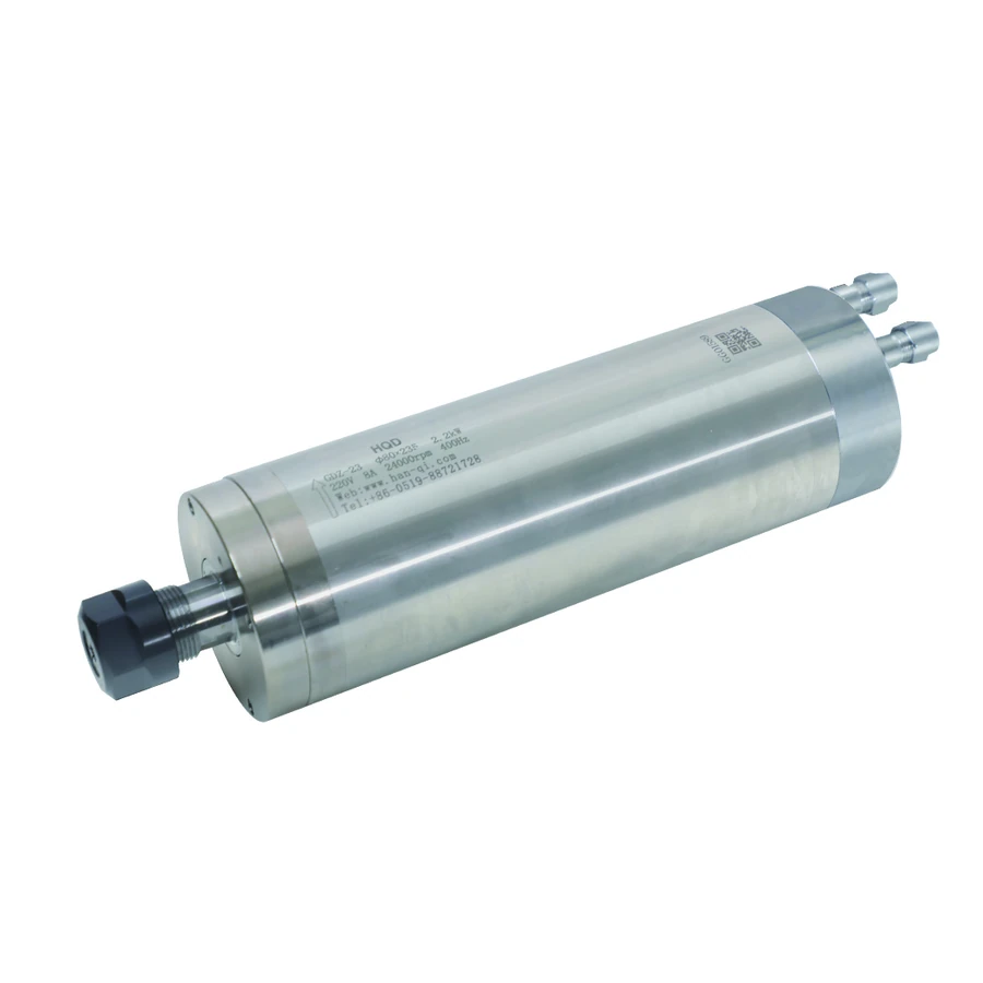
For a manual 2.2 kW comparison, GDF80-24Z/2.2B and GDZ-23 both use ER20 and a 24,000 rpm rated point. The GDF example is air-cooled and the GDZ example is water-cooled. They also differ in overall and clamping dimensions. This is a useful comparison of installation choices, but it does not establish identical cutting behavior or interchangeable mounting.
| Installation question | Air-cooled approach | Water-cooled approach |
|---|---|---|
| Where does heat go? | Into the air path around the spindle | Into a circuit and its heat-rejection equipment |
| What needs space? | Intake, exhaust, fan hardware and access | Hoses, connections, reservoir or cooling equipment |
| What requires attention? | Air-path cleanliness and fan operation | Circuit condition, leaks and equipment operation |
| What is model-specific? | Airflow arrangement and fan electrical supply | Fluid, flow, pressure and thermal limits |
| What else still matters? | Tooling, mount, duty and drive | Tooling, mount, duty and drive |
A buyer comparing only purchase price leaves much of this installation unspecified. Ask the machine builder to identify the supporting equipment and service responsibility for each candidate. Include the planned working environment and production cycle. The resulting comparison should show what must be provided before either spindle can be commissioned.
Plan the actual airflow and fan arrangement
Identify the fan arrangement from the exact spindle drawing and supplied instructions. Do not assume every air-cooled model has a fan driven in the same way. GDL40.5, for example, has a separate 24 V DC fan supply alongside its spindle winding. The fan circuit must be treated as an auxiliary function; the motor power connection does not supply it automatically.
Trace the intended intake and discharge paths with the spindle in its machine position. Consider the bracket, cover, dust shoe and nearby enclosure. A clear product photograph does not show whether the installed machine obstructs the flow. Record the required clearances from the supplied documentation and include access for inspecting the fan and air passages without dismantling unrelated assemblies.
The environment changes how that arrangement is maintained. Dust, chips and residue can accumulate around equipment, so locate inspection points where staff can see and access them. Follow the spindle and machine instructions for cleaning methods. Blowing material into bearings, connectors or an enclosure is not a substitute for an agreed maintenance method.
Describe fan behavior in the commissioning record: what starts it, which supply powers it, and what indication or monitoring is available. Where the machine has a protective response to cooling loss, the integrator should document that response. A routine operator check should compare actual operation with the accepted baseline rather than judge cooling from sound alone.
Design the complete water circuit
Obtain the supplied spindle's fluid specification, required flow, allowable pressure and temperature conditions before selecting a pump or cooler. Record the applicable instructions and compare the proposed supporting equipment against those requirements. Link each circuit condition to the identified assembly and the intended operating environment rather than applying a single set of water-cooling values across HQD models.
Trace the whole circuit from the cooling equipment through the spindle and back. Identify connections, flow direction, hose materials, restrictions, service points and any other component sharing the circuit. A pump's headline flow is not necessarily the flow through the installed spindle: hose length, elevation, fittings and restrictions influence the actual circuit. Have the integrator establish and verify the operating condition.
Heat rejection also needs a defined arrangement. A reservoir, pump and refrigerated cooler serve different functions, and a container of water does not by itself document the ability to manage a production cycle. Record the cooling equipment rating and operating conditions with the intended machine duty. Keep room for service access and the equipment's own ventilation requirements.
Check hoses through the full machine travel. Include bend radius, restraint, moving-cable routing and protection from chips or rubbing. Rear connections remain part of the installed envelope even when the product image displays only the spindle body. A useful layout drawing shows which components remain stationary and which lines move with the Z-axis.
Separate cooling choice from other model changes
Comparing exact examples prevents a cooling decision from hiding a tooling or mounting change. The table below uses documented HQD configurations and calls out an installation difference to review. Their operating points are identifiers for comparison, not a claim that each model will deliver the same result on your machine.
| HQD example | Cooling and tooling | Rated point | Installation evidence |
|---|---|---|---|
| GDF46 base mount | Air; ER20 manual | 2.2 kW; 18,000 rpm; 300 Hz | Base structure; 288.5 mm overall; 7 kg |
| GDF80-24Z/2.2B | Air; ER20 manual | 2.2 kW; 24,000 rpm; 400 Hz | 80 mm body; 125 mm clamp; 269.5 mm overall |
| GDZ-23 | Water; ER20 manual | 2.2 kW; 24,000 rpm; 400 Hz | 80 mm body; 120 mm clamp; 268.5 mm overall |
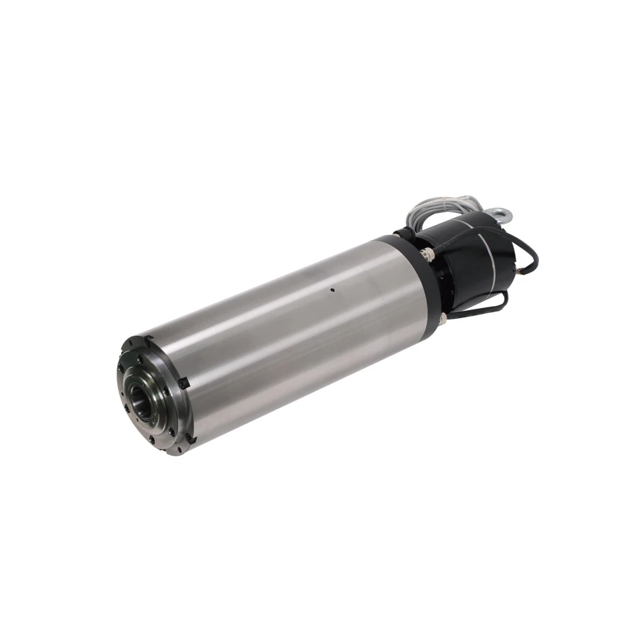
| GDL120 BT30 | Water; BT30 ATC | 5.5 kW; 24,000 rpm; 800 Hz | 120 mm body; 136 mm clamp; 496.5 mm overall |
The ATC example adds holder handling, release air and controls independently of its water circuit. Similarly, changing from a GDF base-mounted unit to a cylindrical GDZ unit changes the support discussion as well as cooling. Keep these differences in the purchase record so the installer is comparing full assemblies.
The series comparison helps separate family-level choices from model details. Use the product drawing for final mounting references, and use the nameplate and supplied operating data for the electrical match. Cooling selection should follow those checks rather than replace them.
Consider ambient conditions and condensation
Record the room conditions and where the cooling equipment will operate. Air cooling depends on its installed air path and environment; water cooling depends on the circuit and cooling equipment conditions. The machine's operating period and the spindle's stated duty also matter. A successful short demonstration does not establish that a longer production cycle stays within the required conditions.
For liquid cooling, assess condensation alongside heat removal. A surface colder than the surrounding air’s dew point can collect moisture, so the circuit specification must account for the actual room and machine environment. Obtain the applicable spindle and cooling-equipment requirements before selecting operating conditions. Settings published for another cooling product do not establish the correct settings for an HQD spindle installation.
Have the integrator record how ambient and circuit conditions will be monitored and what response applies outside the documented limits. Identify any exposed cold surfaces near electrical equipment. Do not choose an arbitrarily low water temperature because colder appears better. The goal is an installation that meets the spindle and cooling-equipment requirements under the expected environment.
If seasonal room conditions change, retain those observations with the maintenance record. That gives a meaningful comparison when an installation that previously worked begins showing condensation or thermal symptoms. It also helps distinguish an equipment fault from a changed environment without inventing a diagnosis from the cooling category alone.
Identify each connection by function
Motor cooling, cutting-zone coolant and tool-release air are separate systems. Cutting fluid addresses the machining process; water through a spindle addresses motor cooling; pneumatic release supports tool exchange. The same machine can require all three. Label circuit function on the installation drawing so hoses and ports are not assigned by appearance or proximity.
Keep electrical auxiliaries separate as well. A fan supply, temperature signal, clamp sensor and motor winding can have different voltages and functions. GDL40.5's 24 V DC fan and sensor connections are a concrete example. Use the supplied wiring diagram to identify terminals, then have the integrator define their interaction with the machine control.
When the cooling type changes during a replacement, identify which old components remain useful and which should be removed or isolated according to the machine design. A water circuit left connected to unrelated equipment still needs its own specification. An added fan needs a suitable supply and control arrangement. Record the changed services in the replacement difference table.
Build a cooling installation record before commissioning
Prepare a record that another technician can use without reconstructing the installation. Include the spindle identity, chosen winding, cooling equipment, route and connection drawings, and the supplied operating limits. Identify where each observation will be taken. This is more actionable than an instruction to check cooling because it names the evidence and the responsible system.
| Record field | What to include | Purpose |
|---|---|---|
| Spindle identity | Full code, physical variant and supplied instructions | Links requirements to the installed unit |
| Cooling equipment | Model, rating and applicable operating conditions | Defines the supporting system |
| Circuit or airflow path | Route, fittings or intake/exhaust arrangement | Makes restrictions and service access visible |
| Auxiliary supply | Fan or sensor supply and control drawing | Separates functions from motor power |
| Monitoring | Measurement location and protective response | Establishes an observable operating baseline |
| Maintenance | Inspection points, method and service record | Supports repeatable routine work |
Complete the record alongside the machine builder, rather than copying settings from a different spindle. Where a requirement is not available, identify the missing supplied document before selecting supporting equipment. Once the design is accepted, retain its revision and record any installation changes so the physical circuit still matches the document.
Verify services before evaluating a cutting process
The commissioning sequence belongs to the machine integrator and the supplied equipment instructions. Cooling-related evidence should include correct connections, suitable equipment operation, accessible service points and documented protection behavior. For a liquid circuit, establish leak checks and observation of the required circulation before evaluating production. For air cooling, establish fan function and an unobstructed path.
Keep these observations separate from cutting acceptance. A spindle can rotate while a cooling connection is wrong, and a satisfactory workpiece does not prove the cooling circuit is suitable for the entire planned duty. Record operating conditions through the agreed commissioning sequence and compare them against the requirements, using suitable instrumentation and qualified personnel.
Retain results by configuration and stage: initial service checks, permitted rotation checks, tool handling where applicable, and representative process evaluation. Note the room conditions and equipment state. This creates a baseline for future changes and provides useful evidence if a later issue occurs during a different production cycle.
Make routine checks specific and repeatable
Build maintenance around the installed arrangement. For air cooling, inspect the agreed intake, exhaust and accessible fan areas for obstruction or changed condition. For water cooling, inspect accessible hoses and connections, the supporting equipment and the circuit observations defined during commissioning. Follow the supplied maintenance methods and intervals; do not substitute a generic calendar for equipment instructions.
Keep a brief record of dates, observations and corrective work. A recurring restriction or leak at the same moving connection points to a different investigation from a one-time equipment shutdown. Changes in fan behavior, circulation or environment should be compared with the accepted baseline and reported with the machine operating state.
Do not continue a production trial to find out whether an unexplained cooling loss is harmless. Use the machine's documented response and qualified service procedure. The useful operator contribution is a clear record of the symptom, affected circuit and machine state, while repair and recommissioning follow the appropriate technical instructions.
Describe a symptom without assigning an unsupported cause
A hot housing, unexpected noise or drive fault can have several causes. Collect the operating point, duration, tool/process information, cooling observations and fault history together. Changing the cooling equipment before recording those facts can obscure whether the original issue involved a restriction, auxiliary supply, operating condition or another component.
| Observation | Evidence to collect | Review direction |
|---|---|---|
| Fan behavior changes | Supply/control state and accepted baseline | Fan arrangement and auxiliary circuit |
| Circuit observation changes | Equipment status, visible restrictions and route | Water system and installed flow condition |
| Moisture appears | Location, room conditions and circuit temperature record | Dew point and environmental suitability |
| Issue follows a process change | Tool, speed, cycle and drive history | Operating point, duty and cooling together |
Use the table to build a service report, not as a remote diagnosis. Attach photographs of the installed route and the exact spindle nameplate. Clear evidence lets the machine builder or supplier review the relevant system and avoids treating every thermal symptom as proof that one cooling category is unsuitable.
Choose a cooling package you can install and maintain
Before requesting a quotation, state which services the machine already provides and which changes are acceptable. Include the exact candidate, working point, production cycle, environment and installation drawing. Ask for the supporting cooling requirements and identify whether equipment, hoses, fittings and auxiliary supplies are included or separately provided.
A hypothetical new router with no water equipment may favor an air-cooled configuration when its documented working point, airflow and mount fit the design. A machine already equipped with a suitable liquid circuit may make a water-cooled candidate practical, after the circuit and spindle requirements are matched. These are planning situations, not a universal preference for one cooling method.
The final decision should identify the spindle and the complete cooling installation it requires. Keep the accepted cooling record with the electrical and mechanical drawings, including the supplied operating limits, equipment identity, routes and service points. Use those records during acceptance and maintenance, and review any later equipment or circuit change against the conditions established for the installed assembly.