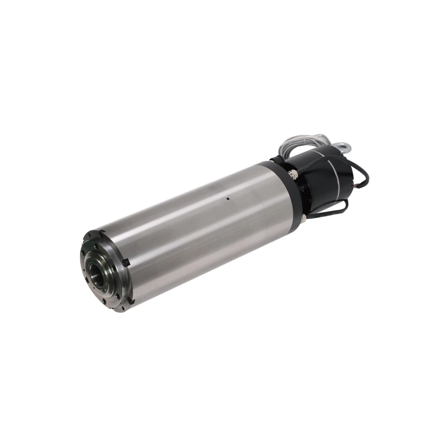
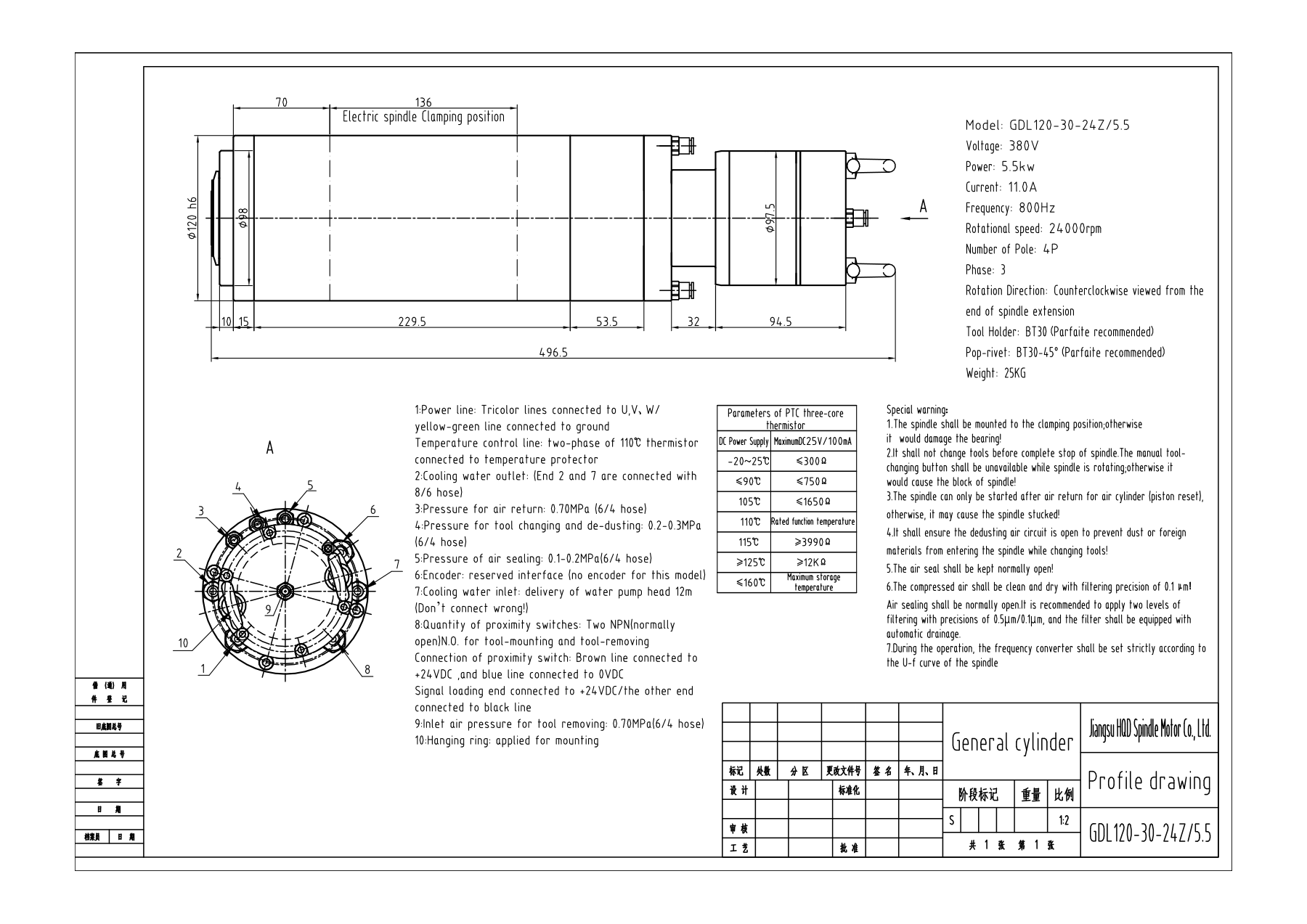
BT30 identifies the taper interface, but an ATC installation also depends on the holder retention arrangement, release movement and magazine geometry. Check the holders, retention hardware and available insertion space against the exact spindle drawing and tooling information. Keep the complete GDL120-30-24Z/5.5 code with that check. A BT30 label on an existing holder establishes a starting point for comparison, not acceptance of the complete automatic tool-change assembly.
Request the pneumatic and electrical connection details for the supplied spindle before commissioning the sequence. The machine must be able to confirm the required clamp and release states before commanding spindle rotation or moving through a tool change. This is an integration check, not a universal wiring recipe: do not copy a pressure value, signal polarity or release timing from another GDL model. Include the controller's available inputs and outputs, the air equipment and the current tool-change sequence in the technical inquiry.
The drawing states that no encoder is fitted to this model and marks an encoder connection as reserved. A connector position is not proof of installed feedback. If your machine needs spindle orientation or another feedback-dependent function, describe that requirement explicitly. Confirm whether the supplied spindle and proposed control arrangement support it before ordering, rather than assuming that a reserved connector can be enabled by changing a VFD parameter.