Key Requirements and Configuration Checks
- A taper name does not establish complete holder compatibility.
- Separate the spindle taper from the collet inside the holder.
- Compare the rack, release system and complete assembly envelope.
Match the proposed configuration to its applicable drawing, operating data and machine requirements. Resolve mounting dimensions, auxiliary services and operating limits before accepting a spindle for the intended installation.
| Interface | HQD example | Installation focus |
|---|---|---|
| ISO20 | GDL40.5 / GDL80 | Different cooling and assembly arrangements |
| ISO30 | GDL70 long / short nose | Nose position and tool-change clearance |
| BT30 | GDL110 / GDL120 | Exact holder, retention and machine requirements |
Separate the spindle interface from the tool clamp
ISO20, ISO30 and BT30 identify spindle-to-holder interfaces. The cutter can be held by an ER collet or another tool-clamping system inside that holder. These are two separate connections. An ISO30 holder carrying an ER32 collet remains an ISO30 holder at the spindle. Buying an ER32 collet does not convert the machine to ISO30, and selecting an ATC taper does not settle the required cutter shank size.
For a retrofit, start with photographs of the existing holder from the side, flange and retention end. Record the complete holder and pull-stud identification where readable. Include the spindle nose, rack pocket and any positioning features. If the machine documentation names a specific holder assembly, keep that reference with the inquiry. A partial label should not be filled in from a similar holder found online.
The useful comparison is therefore not which taper is universally best. It is which documented spindle and holder arrangement can satisfy the machine's tooling, installation and release requirements. Power, speed, weight and cooling must remain in the same comparison. The following HQD examples show different installations within and between the taper groups; they are not a list of interchangeable assemblies.
Compare the HQD examples side by side
The table keeps each interface with its exact spindle. GDL40.5 and GDL80 both use ISO20, yet their rated points, cooling and overall lengths differ. GDL70's ISO30 configurations also distinguish nose structure and power-curve conditions. Use those differences to decide which drawings the machine builder must review.
| HQD configuration | Interface | Output condition | Speed | Cooling | Overall length |
|---|---|---|---|---|---|
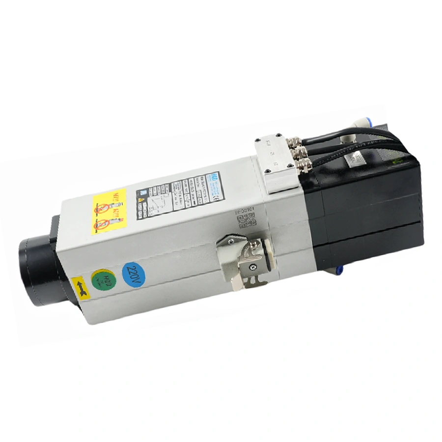
| GDL40.5-ISO20-24Z/2.2 | ISO20 | 2.2 kW rated | 18,000 rated / 24,000 max rpm | Air | 372.5 mm |
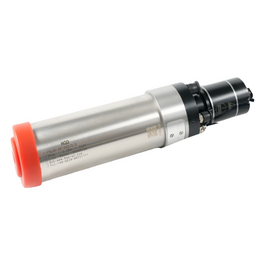
| GDL80-20-24Z/2.2B | ISO20 | 2.2 kW rated | 24,000 rpm rated | Water | 335 mm |
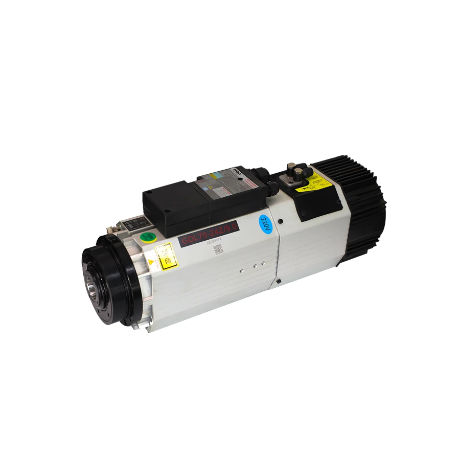
| GDL70-24Z/9.0 short nose | ISO30 | 9 kW at S6-60%, TA20°C | 24,000 rpm | Air | 471 mm |
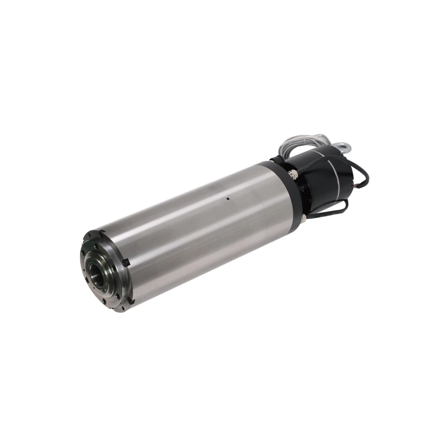
| GDL120-30-24Z/5.5 | BT30 | 5.5 kW rated | 24,000 rpm rated | Water | 496.5 mm |
Do not read overall length as the distance from the machine mount to the tool tip. That location also depends on the mounting reference, nose geometry, holder gauge length and tool projection. Nor does a shared 24,000 rpm figure establish the same drive requirements: GDL80 and GDL120 have documented 800 Hz rated points, while GDL40.5 separates its 300 Hz rated point from its 400 Hz maximum.
ISO20 requires an exact assembly check
The two ISO20 examples offer a focused choice for a machine that already requires this interface. GDL40.5 is an air-cooled assembly with side auxiliaries; GDL80 is a water-cooled configuration with an 80 mm body and 98 mm clamp length. Their identical 2.2 kW rated output does not establish that the same mounting bracket, cooling arrangement or drive setup can be used.
Check the actual holders, retention parts and release arrangement with the supplied spindle documents. Include the largest holder and cutter envelope used by the machine, not just an empty holder. Clearance must remain available during approach, release, withdrawal and travel to the next pocket. The smallest-looking taper does not remove those geometry checks.
For a new build, ask the machine integrator to select the holder family and rack as one documented system. For a replacement, identify which existing parts are intended to stay. A statement that the machine uses ISO20 helps narrow the inquiry, but it should be followed by exact holder identification, mounting measurements, release connections and controls. This makes the difference between a taper shortlist and a usable installation decision.
ISO30 includes meaningful nose and duty differences
HQD's GDL70 ISO30 family contains long-nose, short-nose and water-cooled B configurations. The air-cooled long- and short-nose versions are documented at 551 mm and 471 mm overall length respectively. Those lengths make the assembly comparison important, but the 80 mm difference is not automatically a tool-tip offset: compare the reference dimensions on both drawings before calculating the installed position.
Nose geometry can affect access around a dust shoe, fixture or tool rack. Check the full holder and tool arrangement at every relevant machine position. If more reach is required, do not simply increase tool projection without inspecting the cutter and holder limits. The spindle mounting position, holder gauge length and permitted tool extension all contribute to the result.
The air-cooled GDL70 configurations show 9 kW under S6-60% at TA20°C, while the water-cooled GDL70-24Z/9.0B has a separate 9 kW S1 curve at TA20°C. Retain those duty and ambient conditions beside each power figure. ISO30 identifies the holder interface; it does not establish continuous output, cooling requirements or the permitted production cycle. Record the intended loaded and no-load periods, working speed and installation environment, then compare them with the supplied motor's duty instructions. Confirm the cooling arrangement independently before treating either configuration as suitable for the planned production pattern.
BT30 is a complete tooling choice
GDL110-30-18Z/3.2 and GDL120-30-24Z/5.5 both use BT30. The former is documented at 18,000 rpm and 600 Hz; the latter at 24,000 rpm and 800 Hz. These examples show why a taper group cannot replace the spindle's operating specification. Compare the intended tool speeds and the exact motor/drive combination as well as the holder.
BT30 and ISO30 should not be treated as interchangeable merely because their names contain 30. Verify the exact taper, flange, retention, gauge dimensions and machine handling features. A claim that a pull-stud substitution will work needs support from the spindle and holder suppliers for that complete arrangement. Do not authorize an experimental holder combination from an internet anecdote.
For a machine with existing BT30 tooling, record holder part identifications and the dimensions relevant to its rack and tool measurement system. Ask the integrator to check whether those parts are suitable for the candidate spindle's operating speed and retention system. Compatibility also includes the machine's release sequence and sensing, which must work before the machine is allowed to proceed with a tool change.
Verify retention and release separately
The retention end of the holder is as important as the taper. Identify the supplied retention component and compare its dimensions, engagement and intended use with the spindle documentation. Keep it paired with the holder and spindle configuration. Do not select a pull stud from taper designation alone or assume that visually similar parts have the same engagement.
Separate tool-release air from other pneumatic functions such as sealing or cleaning. The pressure and connection for one function must not be used as a setting for another. Use the exact wiring and pneumatic drawings for the supplied unit. In GDL40.5, fan and sensor auxiliaries use separate 24 V DC circuits; those circuits do not power the spindle winding.
The tool-change controller must evaluate the required state signals and follow the machine builder's sequence. A reserved feedback connector does not establish that the sensor or encoder is fitted. Confirm the installed devices, signal types, release logic and interlocks before commissioning. Review the drive's required operating state, the documented release-air circuit, and the machine clearances as part of the same integration plan. Have the machine and controls integrators define the required checks for approach, release, withdrawal and tool retention, and record the confirmed sequence with the supplied spindle's wiring and pneumatic drawings.
Check the rack and machine envelope
Map the tool-change path using the spindle nose, holder and largest relevant cutter. Include approach height, rack pocket location, release travel, withdrawal clearance and adjacent holders. A tool that clears the workpiece during cutting can still collide during exchange. Check the dust shoe and routed services in the same model of the machine envelope.
| Check | Evidence to gather | Who needs to confirm it |
|---|---|---|
| Holder and retention identification | Markings, side view and retention-end dimensions | Spindle and tooling suppliers |
| Rack pocket and handling features | Pocket drawing, holder flange and spacing | Machine integrator |
| Installed tool-tip position | Mount reference, nose, holder and cutter projection | Machine builder |
| Tool-change movement | Approach, release and withdrawal envelope | Machine integrator |
| Release and sensing | Exact supplied wiring and pneumatic drawings | Controls integrator |
For an existing machine, compare the current installed geometry before replacing parts. If the nose position changes, review tool length measurement, offsets, travel limits and rack alignment as part of the retrofit. Do not assume that retaining the same taper preserves these settings. After integration, acceptance must follow the machine builder's commissioning procedure with the actual tool inventory.
Use ISO25 and BT40 as extension choices
HQD also includes ISO25 and BT40 configurations. They should enter the comparison when the machine and tooling requirement calls for them, rather than serving as automatic upgrade steps from ISO20 or BT30. The installation, operating point and exact retention system need their own checks.
| Configuration | Interface | Rated output | Rated point | Installation information |
|---|---|---|---|---|
| GDL100-25-24Z/2.5 | ISO25 | 2.5 kW | 24,000 rpm / 400 Hz | 100 mm body; 130 mm clamp length |
| GDL125-40-12Z/7.5 | BT40 | 7.5 kW | 12,000 rpm / 600 Hz | 125 mm body; 618 mm overall length |
These models are useful reminders that interface size, power and speed must be read independently. A 7.5 kW BT40 configuration documented at 12,000 rpm is a different operating choice from a 24,000 rpm ISO30 configuration. Confirm any optional feedback and auxiliary hardware separately from the catalog interface name. An option is not evidence that the quoted unit includes it.
Plan tool measurement when the spindle changes
A retained taper and holder inventory can simplify a replacement project, but the installed gauge reference still needs checking. Record the machine mounting reference, spindle nose reference, holder gauge length and tool projection as separate dimensions. Compare the old and new spindle drawings before applying any change to tool offsets. Overall assembly length includes rear structures and does not directly describe the new cutting-point position.
For a machine using a fixed tool setter, confirm that the intended holders and cutters can reach the measurement position with the required travel and clearance. For a machine using another measurement procedure, have the integrator review how tool lengths will be established after replacement. The spindle, setter, rack and fixtures need to share a consistent reference system.
Include the shortest and longest intended assemblies in the geometry review. A rack pocket can fit the empty holder while an adjacent cutter or dust shoe interferes during approach. Check relevant neighboring pockets and the actual exchange path, not just a static front view. Record which holder and cutter combinations have been evaluated so later additions to the tool inventory trigger a focused review.
Prepare a commissioning record with holder identities, rack positions, tool measurement method and the machine builder's required release-state checks. Have the integrator confirm the relevant sequence and interlocks before accepting automatic operation. The record should also identify changed offsets and travel limits, so maintenance personnel can understand why an earlier machine setting no longer applies.
This is especially useful when choosing between long- and short-nose ISO30 configurations or changing to a BT30 system. Treat the spindle decision as part of the tooling and geometry package. A supplier can quote the motor from its model code; the machine project must additionally resolve how the entire tool inventory will be measured, exchanged and positioned.
Prepare the tooling compatibility record
There are three common starting situations. If you want to retain holders, provide their exact identity and the present rack geometry. If you want to change interface, plan the holder inventory, rack and control integration together. If you are adding ATC to a manual machine, include pneumatic release, sensing and tool length handling in the machine project before narrowing spindle power.
Prepare a short record containing the machine model, present spindle, holder and retention parts, representative cutters, rack drawing and control connections. Mark the components to be retained and the components to be changed. This gives the supplier a concrete compatibility question instead of a broad request for a compatible ATC spindle.
Complete the shortlist after the holder, retention system, mounting and release requirements have been checked. For an ISO20 installation, compare GDL40.5 and GDL80 against the required cooling services, drive frequency and assembly envelope. For ISO30 or BT30, retain the exact GDL70 nose configuration or GDL120 holder and retention specification. In cabinet production, list the profiles, grooves and hardware operations in sequence, record the manual exchange and measurement time, and confirm that the planned rack and controls support the holder inventory. These operating requirements determine whether the proposed ATC installation addresses the production need.