Key Requirements and Configuration Checks
- Build the selection around the recurring operation and cutter.
- Check feed capability and workholding alongside spindle power.
- Compare manual changing with the complete ATC installation.
Match the proposed configuration to its applicable drawing, operating data and machine requirements. Resolve mounting dimensions, auxiliary services and operating limits before accepting a spindle for the intended installation.
| Production task | Primary check | Record |
|---|---|---|
| Panel profiles and grooves | Tooling, feed and panel support | Cutter, sheet, toolpath and holding method |
| Multiple cabinet operations | Tool changes and holder inventory | Actual job sequence and exchange conditions |
| Long detail paths | Speed, projection and operating duty | Cycle pattern, tool limits and cooling |
Start with the cabinet production sequence
A CNC spindle for MDF or plywood must be selected around the operations the machine will repeat. Cutting a panel profile, machining a groove, drilling hardware positions and finishing an edge are different jobs. List them in the order used in production, together with the required cutter and tool shank. This reveals whether the main need is an operating point, a tooling range or a reduction in manual exchanges.
Keep the panel construction in the job record. MDF, plywood and solid wood should not be treated as a single material with one universal cutting setting. Plywood can include different face layers and internal construction; coatings and edge-finish requirements can change the tool choice. Obtain cutter recommendations for the actual stock and operation. A spindle specification alone cannot decide the required cutting-edge geometry.
For an existing machine, record a representative job that meets the required finish and a job that currently causes difficulty. Compare tool condition, hold-down, projection and programmed feed as well as spindle settings. For a new machine, provide the recurring sheet sizes, workholding arrangement and operation sequence to the builder. Use these requirements to form a shortlist before deciding which power figure to order.
Turn each task into a tooling requirement
Use the recurring tool inventory as the first selection filter. Profile cutting, grooves and finishing passes can require different cutters even within one cabinet job. Record the actual shank diameter separately from the cutting-edge diameter, and identify a compatible individual collet for every metric or inch shank. A 1/4-inch shank is 6.35 mm and should not be recorded as a 6 mm tool. For ATC equipment, include the complete holder, external taper and retention arrangement as well as the collet, then check the assembled cutter's speed, projection and clearance limits.
| Task | Tooling information to gather | Machine condition to inspect |
|---|---|---|
| Panel outline | Cutter geometry, diameter and shank | Panel support and hold-down near the final cut |
| Grooves and rebates | Cutter, required depth and passes | Feed control and remaining workpiece support |
| Hardware features | Required tool and holder | Positioning, tool measurement and access |
| Edge finishing | Geometry and finish requirement | Stable tool projection and workholding |
| Detail carving | Small tool, neck and projection | Long-cycle operation and machine motion |
This table does not assign a universal power to each task. Two machines performing the same groove can use different cutters and engagement, and may be limited by different factors. The purpose is to collect the conditions that a spindle supplier can compare. If a tool cannot fit the proposed collet system, resolve that mismatch before discussing more aggressive passes or higher production rates.
Relate RPM to the machine's real feed capability
Spindle speed and feed rate need to be considered with the cutter's cutting edges and recommended chip load. For a simple feed calculation, feed equals RPM multiplied by the number of cutting edges and chip load per tooth. Use consistent units. The cutter manufacturer's recommendation provides the starting conditions; the spindle's maximum speed is not a substitute for them.
As an arithmetic example only, suppose the chosen tool documentation calls for 0.10 mm per tooth at the intended engagement. With two cutting edges and 18,000 rpm, the calculated feed is 18,000 × 2 × 0.10 = 3,600 mm/min. If actual feed falls to 1,800 mm/min while that speed remains, the corresponding arithmetic chip load is 0.05 mm per tooth. These assumed values demonstrate the relationship; they are not recommendations for a particular HQD spindle, wood or cutter.
Short segments, corners and acceleration limits can keep actual feed below the programmed value. Check the toolpath and machine capability before choosing a high RPM merely because it appears on the spindle label. If the cutter's required conditions and the machine's feed cannot be reconciled, revise the tool or process with the machine and tooling suppliers. Changing motor power alone will not resolve the motion constraint.
Compare manual spindle configurations accurately
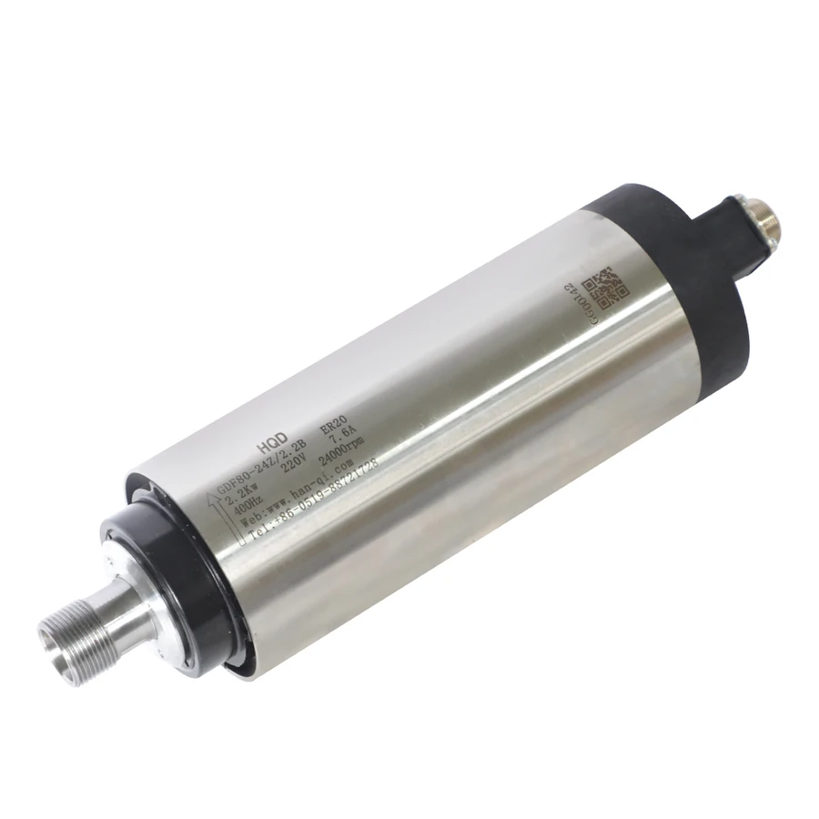
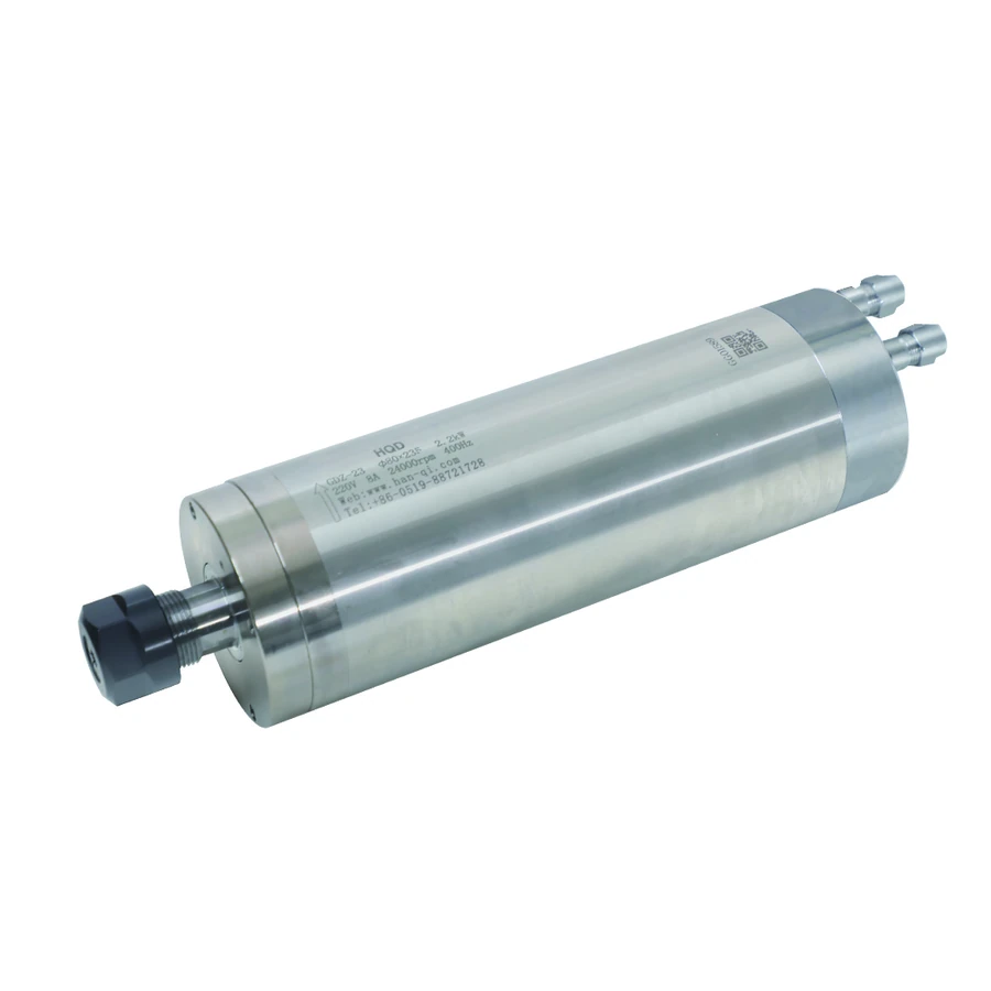
GDF80-24Z/2.2B and GDZ-23 provide two manual ER20 examples with 2.2 kW rated output and 24,000 rpm rated speed. They differ in cooling and installation details. Their similar headline values make them useful for a focused comparison, but not for an assumption that a mount or cooling circuit can be reused.
| Configuration | Tooling | Cooling | Body diameter | Overall length | Clamp length |
|---|---|---|---|---|---|
| GDF80-24Z/2.2B | ER20 manual | Air | 80 mm | 269.5 mm | 125 mm |
| GDZ-23 | ER20 manual | Water | 80 mm | 268.5 mm | 120 mm |
For an air-cooled installation, inspect the intended airflow path, access to cooling hardware, and the effects of the enclosure and extraction arrangement. For a water-cooled installation, identify the circulation equipment, compatible fittings, hose routing and space needed for the supplied connections. Obtain the exact spindle's coolant, flow and temperature requirements before selecting or reusing the circuit. Check the planned production cycle and installation environment against those instructions; values from another model do not establish suitable cooling conditions for the proposed assembly.
Manual changing can remain appropriate when the job uses one recurring tool or when changes fit the production pattern. The decision should include actual exchange, measurement and operator time. A manual spindle with the desired power does not solve interruptions caused by multiple cutters; equally, an ATC assembly does not automatically shorten machining time when the job is constrained by feed or workholding.
Decide whether the sequence justifies ATC
Record the actual tool sequence across a batch, not only the number of distinct tools on one drawing. A cabinet job can group operations across several panels, which may reduce manual exchanges. Alternatively, keeping all operations on one panel can create a stronger case for automatic changing. Compare the intended workflow with its requirements for tool length handling, operator attendance and part identification.
Build a time record with cutting, exchange, tool measurement, loading and hold-down steps kept separate. Use measured times where available. If you use estimates, label them as planning assumptions and do not convert them into a claimed productivity improvement. Automatic changing is useful when its complete installation addresses a recurring interruption, and the machine can perform exchanges reliably with its actual holder inventory.
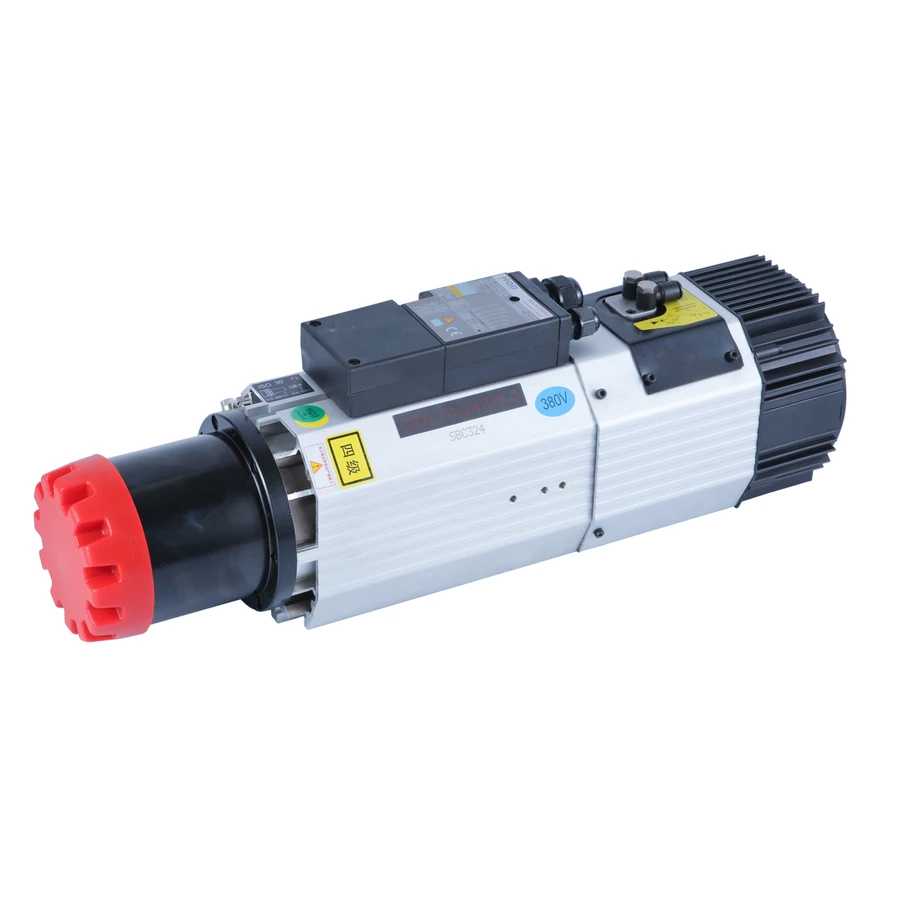
An ATC project requires a compatible rack, retention system, release-air circuit, state signals and interlocks. Identify the exact ISO20, ISO30 or BT30 holder assembly and verify its flange, retention parts and handling geometry against the spindle and rack. Include the largest relevant cutter, tool measurement method and exchange clearances in the machine review. Resolve these requirements before ordering a spindle to reduce manual changes. The machine builder's tool-change sequence and verified controls integration are part of the production installation, and must be planned with the holder inventory rather than after the motor arrives.
Check nose geometry and extraction clearance
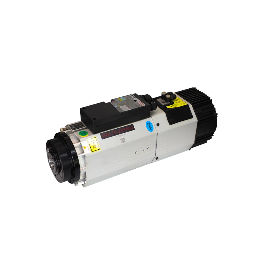
For the GDL70 ISO30 examples, long- and short-nose assemblies have documented overall lengths of 551 mm and 471 mm. Use the drawings to compare the installed mounting reference, nose and holder position. The overall length difference alone is not a measurement of tool-tip movement. Holder gauge length and tool projection also contribute to where the cutter sits.
| GDL70 configuration | Interface | Cooling | Overall length | Power-curve condition |
|---|---|---|---|---|
| Long nose | ISO30 | Air | 551 mm | 9 kW, S6-60%, TA20°C |
| Short nose | ISO30 | Air | 471 mm | 9 kW, S6-60%, TA20°C |
Include the dust shoe, extraction hose, fixture height and tool-change path in the clearance review. A hood that clears a cutting pass can still interfere with the rack or another holder. Verify access for the largest intended tool and for the empty spindle during release. Do not solve an interference simply by extending the cutter farther than its tooling instructions allow.
The product photographs help distinguish the assemblies, while the drawings provide the installation evidence. Have the machine builder review the complete arrangement, including services and permitted motion. Keep the exact long- or short-nose configuration on the quotation so that the installation discussion is not lost under a shared GDL70 model name.
Match the cycle to the documented working conditions
Panel production often combines loaded cutting, travel, tool exchange and loading. Record which stages the spindle experiences as loaded operation and which as running without a cutting load. Compare that pattern with the supplied motor's documented operating conditions and cooling. A successful sample panel cannot by itself establish operation over repeated batches or a complete shift.
The air-cooled GDL70 configurations attach S6-60% and TA20°C to the 9 kW figure. Retain both conditions when comparing output, and do not describe that figure as unrestricted continuous power. S6 refers to alternating loaded and no-load operation without a rest or de-energized interval; the percentage identifies the loaded portion of the specified cycle. Record the planned cutting and no-load periods and obtain the supplied motor's applicable cycle requirements. Check the actual ambient environment and cooling arrangement separately, because a successful panel or a nominal 60% time estimate does not establish compliance with the documented rating.
For long detail paths, keep tool speed limits, cooling and process load in the same review even if the cut appears light. Record changes in tool condition, material or engagement that alter the load. The production check should be for the actual planned cycle, not an average assembled from unrelated demonstrations. Ask for the operating documentation needed to resolve any gap before using an assumed duty pattern to justify the purchase.
Use three production scenarios
A panel shop performing one recurring profile operation can start with manual ER20 configurations and compare the exact cooling installation, mount and operating requirement. Its workholding at the final perimeter cut deserves special attention because loss of support can affect the process independently of spindle power. Record the successful tool and job conditions before choosing an alternative spindle.
For cabinet workflows involving profiles, grooves and hardware operations, compare the complete sequence. List the required holders, usable rack pockets, tool length management and exchange positions. Consider an ISO30 GDL70 configuration when its holder interface, mounting envelope, operating point and services meet the machine requirements. Define acceptance using a representative panel and record cutting, exchange, measurement and loading time separately. The selected spindle's duty and cooling conditions must support that cycle; neither its power rating nor its automatic tool-change capability establishes a particular cabinet throughput.
A shop adding occasional solid-wood detail work should keep the small-tool inventory and projection limits visible. The production spindle used for panel work may or may not satisfy those tool requirements. Check the available holders and speed conditions instead of assigning solid wood a single preferred spindle power. Where the process needs different tooling, plan the tooling package before changing the motor.
Compare production time by operation
Build a time record for a representative cabinet sheet. Separate positioning and setup, cutting, manual tool changes, tool measurement, part removal and cleaning. Use observed times from the current process where available, and mark proposed times as estimates. This reveals whether spindle output, tool exchange or another part of the production sequence is the useful target for improvement.
For example, a job with several short cutting operations and repeated manual changes can spend a substantial share of its cycle outside the cut. Increasing motor power would need a demonstrated process change to reduce cutting time, while ATC addresses a different part of the record. Compare both proposals against the actual sequence, including the rack, measurement and control integration required for automatic changes.
Also group similar parts where the production requirements allow it. The machine supplier can help evaluate whether batching operations reduces manual changes or creates extra setup and holding work. The goal is to select an installation that serves the real production pattern. Do not calculate a promised throughput increase from nominal spindle kW or from tool-change capability alone.
Prepare the production specification
Use a job sheet that captures one representative part or recurring family of parts. Add the differences that matter, such as face finish, groove geometry, cutter changes or panel holding. This is more useful to a machine builder than a request for the best woodworking spindle.
| Requirement | What to record | Why it affects selection |
|---|---|---|
| Stock and operations | Panel construction, coatings and job sequence | Defines cutter and workflow requirements |
| Tool inventory | Cutting geometry, shanks, holders and projection | Filters tooling and access |
| Feed capability | Actual motion on representative paths | Checks whether RPM and feed can work together |
| Workholding | Support and release of cut parts | Separates fixture limits from spindle limits |
| Production cycle | Loaded, no-load and exchange stages | Supports duty and cooling comparison |
| Installation | Mount, dust shoe, rack and routed services | Checks the complete machine envelope |
Attach the present spindle nameplate, machine drawings, cutter specifications and drive data, then identify one exact candidate and the documents needed to check it. For a manual-spindle comparison, assess 0.8, 1.5 and 2.2 kW configurations by their actual tooling interface, working point, mount dimensions and moving mass. State which current components will remain and which changes the machine builder has accepted. Retain the proposed duty and cooling conditions with the candidate, and validate the process on the intended machine before using assumed cutting speeds or batch times to justify the purchase.