Key Requirements and Configuration Checks
- Compare the required tool shank before choosing a power class.
- Check the exact dimensions and weight, even when power matches.
- Match the supplied winding and operating point to the drive.
Match the proposed configuration to its applicable drawing, operating data and machine requirements. Resolve mounting dimensions, auxiliary services and operating limits before accepting a spindle for the intended installation.
| Power class | HQD example | First decision |
|---|---|---|
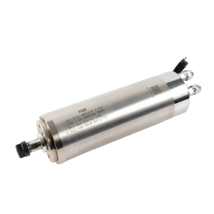
| 0.8 kW | GDZ-18-2 | ER11B tooling and 65 mm installation |
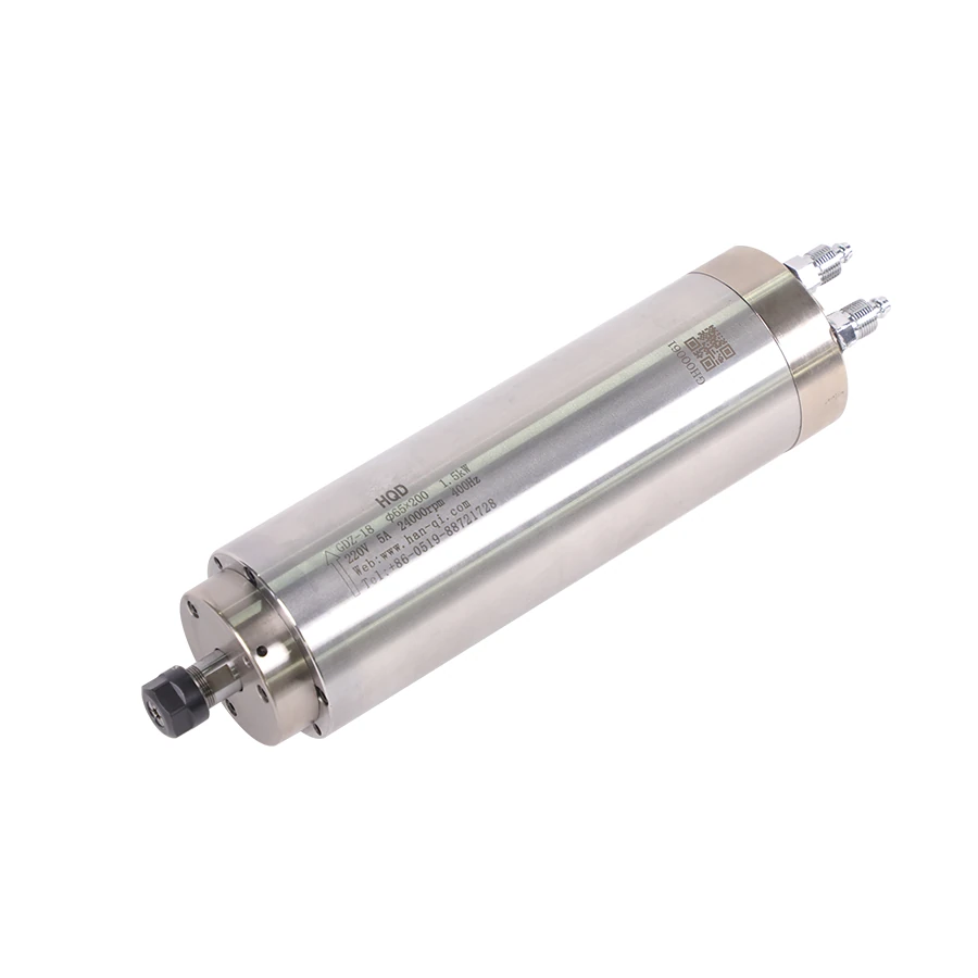
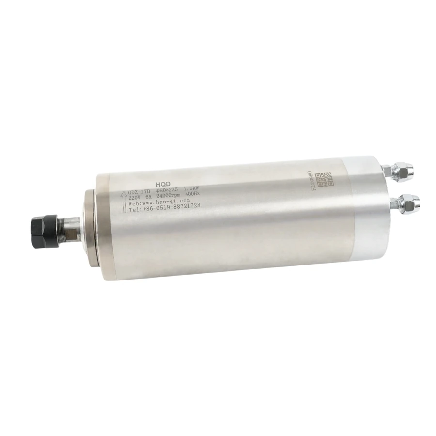
| 1.5 kW | GDZ-18 / GDZ-17B | ER11 or ER16 and different body sizes |
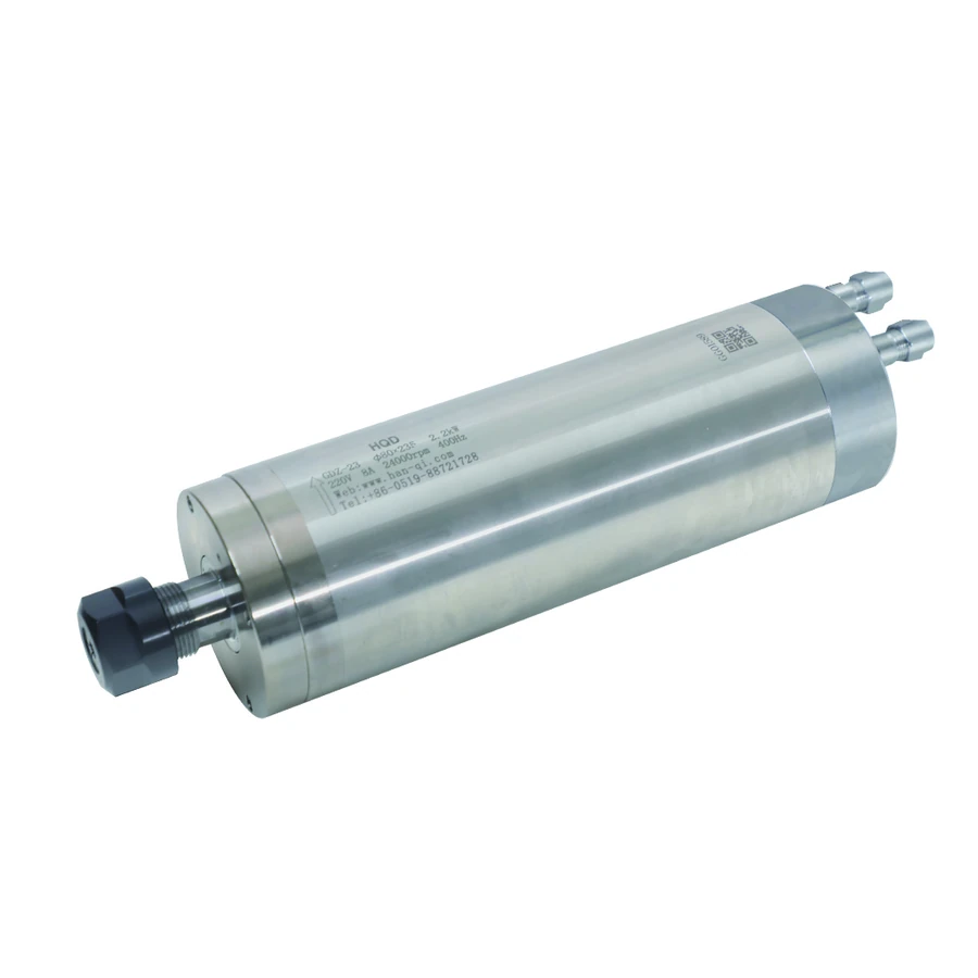
| 2.2 kW | GDZ-23 | ER20 tooling and 80 mm installation |
Choose the power class around the job
A 0.8 kW, 1.5 kW or 2.2 kW CNC spindle is a motor and tooling assembly, not a complete statement of cutting capacity. Write down the material, operation, cutter and production pattern first. A long engraving path with a small cutter creates a different requirement from repeated slotting, even when both jobs are performed on the same router. The comparison becomes useful when you know which limitation you are trying to remove.
Start by identifying the present limitation. If the required tool shank will not fit, compare collet interfaces. If the spindle mount is unsuitable, compare mechanical dimensions. If the machine cannot maintain the required feed through corners, extra motor power does not remove that motion limit. If the drive trips, record the fault and operating conditions before assuming that a higher-power spindle is the answer. These are separate questions that need separate evidence.
The three classes below provide a way to narrow the shortlist. They do not establish a fixed maximum cut depth or a material-to-power rule. For an existing machine, record a representative toolpath and the settings that currently work. For a new machine, obtain the machine builder's spindle mass, tooling and operating requirements. Keep the most demanding recurring operation in the comparison, rather than selecting from the easiest demonstration cut.
Compare real HQD configurations
The HQD examples show why power cannot stand in for dimensions or tooling. GDZ-18 and GDZ-17B are both rated at 1.5 kW and 24,000 rpm, but they use different collet interfaces and body diameters. A purchase described only as a 1.5 kW water-cooled spindle leaves those important choices unresolved. The full model code must stay with the drawing and quotation.
| Configuration | Rated output | Interface | Body diameter | Overall length | Weight |
|---|---|---|---|---|---|
| GDZ-18-2 | 0.8 kW | ER11B | 65 mm | 224 mm | 4.5 kg |
| GDZ-18 | 1.5 kW | ER11 | 65 mm | 235.5 mm | 4.5 kg |
| GDZ-17B | 1.5 kW | ER16 | 80 mm | 241 mm | 5 kg |
| GDZ-23 | 2.2 kW | ER20 | 80 mm | 268.5 mm | 6 kg |
All four examples are water-cooled manual-tool-change configurations rated at 24,000 rpm. The table deliberately holds those attributes steady while showing the differences that matter to tooling and installation. It also shows that a lower power figure does not necessarily mean lower mass: GDZ-18-2 and GDZ-18 are both documented at 4.5 kg. Use the exact values instead of a generic weight estimate for each power class.
Decide from the tool inventory
Make a list of the shank diameters used on the jobs you actually quote. Keep shank diameter separate from cutting diameter: a cutter can have a wide cutting head on a smaller shank. An ER interface must accept the shank through the correct individual collet. It does not approve the cutter's cutting diameter, maximum speed or load. Check those limits in the tooling documentation.
For a machine using small tools throughout a long engraving cycle, the first question may be whether the current tool system, speed control and spindle condition are satisfactory. For a machine that needs a wider range of shanks, the available ER interface becomes an early filter. GDZ-18's ER11 and GDZ-17B's ER16 demonstrate that you can change the tooling envelope within the same 1.5 kW power class. That is a more precise comparison than simply upgrading wattage.
Do not assume that a larger collet family includes every collet you need. Specify the actual metric or inch shanks, required individual collets and compatible nut when requesting the package. A 6 mm shank and a 1/4-inch shank are different sizes. Cleaning, correct assembly and the prescribed tightening procedure also matter; additional motor power cannot compensate for a poorly held tool.
Check the machine and mount before increasing mass
The move from a 65 mm body to an 80 mm body changes the mounting requirement. Compare the usable support area, overall assembly length, nose position and rear clearance, not just the clamp bore. A new bracket also changes how far the cutting point sits from the supporting structure. Have the machine builder check that arrangement and the Z-axis load before treating the upgrade as a simple motor exchange.
On GDZ-23, the documented clamp length is 120 mm. That dimension is part of the mechanical comparison, not permission to clamp any part of the housing. Use the specified support area and the actual bracket drawing. Add coolant hoses and power-cable bends to the clearance check. A photograph with the trailing accessories removed is useful for seeing the body, but installation still needs room for the supplied connections.
The table's 5 kg and 6 kg figures for GDZ-17B and GDZ-23 do not tell you whether your machine can carry either assembly. Acceleration, bracket stiffness, cable forces and any dust shoe add to the installation question. Request the allowed spindle mass and mounting arrangement from the machine supplier. Avoid choosing a Z-axis motor or bracket from spindle power alone; those selections require the machine's mechanical information.
Separate spindle output from electrical supply
The catalog power is the spindle's documented output rating. It is not a wall-socket consumption figure, and it does not establish which VFD can run the motor. Check the supplied winding voltage, rated current, frequency and the drive's output capability together. The drive's input supply is a separate specification. A shop supply description such as 220 V is not enough to complete that matching exercise.
A spindle specified for 24,000 rpm at 400 Hz requires a drive whose output range and motor setup support that operating point. Other HQD configurations reach the same speed with different pole counts and electrical frequencies, so settings from an equal-power motor may be unsuitable. Check the supplied spindle's winding voltage and rated current as a matched pair, its required output frequency, and any separately powered fan or sensor circuits. Confirm the drive's input supply and output capability independently, using the exact motor and drive documentation before commissioning.
Ask for the motor and VFD specifications before placing the order. If the intended upgrade requires a different drive, include electrical enclosure space, control interfaces and commissioning in the machine discussion. Do not infer a 110 V winding from a generic online listing for the same power class. Keep current and voltage on their documented configuration, and let the electrical installer verify the circuit and protective equipment.
Use three selection scenarios
Scenario one is a machine running small-shank tools on long detail paths. Begin with its permitted spindle mass, existing clamp and actual tool sizes. A 0.8 kW configuration can remain on the shortlist when those conditions fit and the process requirement supports it. The decision should come from the job and operating data, not an assumption that detail work always needs the smallest motor. Check continuous operation and cooling separately.
Scenario two is an owner comparing 1.5 kW configurations. GDZ-18 and GDZ-17B provide a focused tooling-and-mount comparison: ER11 versus ER16, 65 versus 80 mm body, and different mass and length. If the desired tools fit the first interface and the existing machine supports that configuration, the larger body is not automatically necessary. If the inventory requires the second interface, the mounting implications must be included in the change.
Scenario three is a router preparing for ER20 tools and recurring slotting or production tasks. GDZ-23 supplies a 2.2 kW, ER20, 80 mm example. Confirm cutter limits, machine feed capability, workholding, operating duty and drive suitability before concluding that its extra rated output will improve production. A cut that is limited by fixture vibration or an unsupported panel edge needs a mechanical correction; a power upgrade should not be used to hide the cause.
| Observed requirement | Compare first | Evidence needed |
|---|---|---|
| Existing tools do not fit | Collet interface and nut | Tool shank inventory and tooling specifications |
| Mount cannot support the assembly | Body, clamp and complete envelope | Machine drawing and permitted mass |
| Motor slows or drive trips | Process load and electrical match | Toolpath conditions, fault record and drive data |
| Many tool changes interrupt work | Manual versus ATC installation | Tool sequence, rack, controls and release requirements |
Keep production duty in the comparison
A short successful cut does not demonstrate sustained operation over a full shift. Record how long the spindle spends cutting, running without cutting and changing tools. Check the motor's documented working conditions and cooling requirements. If a higher output appears on a curve with a duty or temperature condition, keep that condition attached to the number. Do not compare it directly with an unqualified rated output.
A manual ER spindle and an ATC spindle also solve different workflow problems. More power will not remove manual tool-changing interruptions. Conversely, automatic tool change adds mechanical, pneumatic and control requirements that are absent from a straightforward manual-spindle comparison. If those interruptions are the production bottleneck, review the complete ATC installation before increasing power on an otherwise suitable manual assembly.
Define the measurable result required from the change: a tool that fits, a documented operating point, fewer manual changes, or a verified improvement on a representative job. Record the present result and the proposed acceptance condition so the supplier can assess a specific requirement. For an output comparison, identify the power available at the intended working speed and retain the curve's duty, cooling and ambient conditions. A headline power rating does not establish available power throughout the speed range, and a calculation cannot supply operating evidence that the manufacturer has not documented.
Compare an upgrade without changing every variable
Suppose a router currently has a GDZ-18 with a 65 mm mount and needs to use a tool supplied on an 8 mm shank. Begin with the tool supplier's shank and assembly requirements. The standard ER11 tooling range does not settle that inventory requirement, so compare the ER16 candidates. GDZ-17B brings an 80 mm body, while GDZ-18B provides a 65 mm, 1.5 kW ER16 example. This comparison reveals another candidate before making power the deciding factor.
GDZ-18B is documented at 254.5 mm overall length, 4.5 kg and 110 mm clamp length. Even with a 65 mm body, it needs an exact drawing comparison with the installed GDZ-18. Check where the new nose and tool tip would sit, the available support length and the service connections. Retaining the nominal clamp bore does not prove that all installation details remain suitable.
Once a mechanically suitable candidate is identified, compare the drive and production requirement. If the current job already meets its output requirement and only the shank inventory changes, the inquiry can focus on a suitable tooling configuration. If the production operation also changes, review its operating point independently. This prevents an unnecessary chain of bracket, drive and motor changes based on an unresolved tooling question.
Record the existing setup as the baseline: tool, working speed, feed, engagement, finish requirement and accepted result. Record the proposed setup alongside it, marking each changed component. The supplier can then identify which drawings or settings need review, and the machine builder can plan a useful acceptance comparison. Keep the original configuration available in the record even after the new setup is accepted.
Prepare a procurement record
Complete the table with your actual machine and job data. Missing items should remain questions in the inquiry, especially dimensions and electrical values that cannot be read from the existing nameplate. Attach clear photographs of the spindle, bracket, tooling and connections. Include a representative operation, tool size and working speed so the comparison is connected to a real task.
| Item to record | Your measurement or requirement | Document to compare |
|---|---|---|
| Full model and physical configuration | Record every suffix | Nameplate and exact product drawing |
| Tool shanks and cutter limits | List metric and inch sizes separately | Collet and cutter documentation |
| Clamp and Z-axis installation | Bore, support area, mass and clearance | Machine builder's mounting limits |
| Working speed and duty | Typical speed and cycle pattern | Spindle rating and operating curve |
| VFD and supply | Input, output, current and frequency | Drive manual and supplied winding |
| Cooling and connections | Circuit, routing and available space | Installation and connection drawings |
Compare GDZ-18-2, GDZ-18, GDZ-17B and GDZ-23 against the required shanks, available mount, permitted moving mass and documented working point, then specify one complete configuration for quotation. Confirm the supplied winding, compatible drive and cooling connections before adding quantity and destination. Where the comparison requires a different bracket, altered clearances or another drive, have the machine builder resolve those changes before ordering. The selected spindle should satisfy the installation and production requirement as a whole, rather than simply carry the preferred power rating.