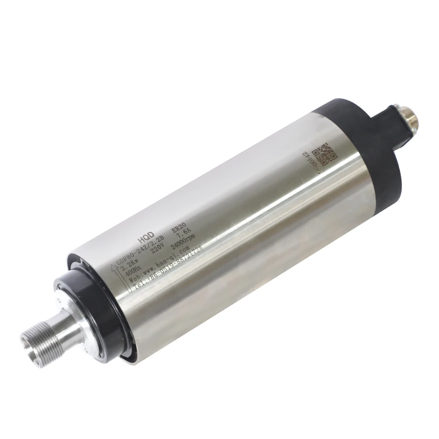
GDF80-24Z/2.2B spindle

GDF SERIES · MANUAL

HQD GDF80-24Z/2.2B ER20 spindle motor

2.2 kW ratedER20Air-cooled24,000 rpm ratedØ80 mm269.5 mm overall

HQD GDF80-24Z/2.2B is an air-cooled manual ER20 spindle rated at 2.2 kW and 24,000 rpm. Retain the B suffix to identify its ER20 nose, 269.5 mm assembly and 125 mm clamp region. Check the 80 mm body against the mount, then choose 220 V / 7.6 A or 380 V / 4.4 A and review the 400 Hz drive capability.

Browse the GDF spindle range →

MODEL SELECTION

Is this the right GDF80-24Z/2.2B configuration?

BEST FIT

Choose this configuration if:

  • The process uses manual ER20 tooling at the documented 2.2 kW / 24,000 rpm point.
  • The machine supports an 80 mm body with the specified 125 mm clamp region.
  • The selected winding and applicable air-cooling path can be integrated with the machine.

CHECK BEFORE ORDERING

Confirm these details first:

  • Keep the B suffix with the model so the ER16 non-B version is not substituted.
  • Select 220 V / 7.6 A or 380 V / 4.4 A as a complete supplied winding pair.
  • Check the support location, 269.5 mm assembly, nose datum and 400 Hz drive requirement.
Selection and installation topics

SPECIFICATIONS

Read the operating conditions.

This air-cooled spindle uses ER20 tooling. Power: 2.2 kW rated. Speed: 24,000 rpm rated. Installation dimensions and weight: 80 mm body diameter, 125 mm clamping length, 269.5 mm overall length. Winding options: 220 V / 7.6 A or 380 V / 4.4 A.

Swipe or scroll across to see all columns.

Use the left and right arrow keys to scroll this table.

Output and duty
Rated power (kW)2.2
Rated speed (rpm)24,000
Tooling and mounting
Tool interfaceER20
Tool changeManual tool change
Electrical
Frequency (Hz)400
Dimensions and weight
Body diameter (mm)80
Overall length (mm)269.5
Clamping length (mm)125
Cooling and feedback
CoolingAir-cooled

Winding options

Match the voltage and current of the winding you intend to order.

  • 220 V · 7.6 A
  • 380 V · 4.4 A

2.2 kW at 24,000 rpm on the B-suffix assembly

The documented rated point is 2.2 kW at 24,000 rpm, with 400 Hz listed. Keep the B suffix and ER20 description visible in the selection. The non-B GDF80 shares the motor figures and diameter but uses ER16 and a 263.5 mm assembly. Shared output and speed do not identify the same nose or support arrangement.

Describe the cutter, working speeds and load cycle rather than selecting only from the rated point. The figures do not establish full output at every lower speed. Request applicable operating information when sustained work elsewhere in the speed region is decisive. The GDF46 ER20 alternatives operate at a documented 18,000 rpm point and use another support architecture, so compare the process and mount together.

Select the complete electrical pair for the ER20 model

The documented winding options are 220 V / 7.6 A and 380 V / 4.4 A. They describe separate supplied motor configurations. Choose one complete pair and keep it with the B-suffix model in the quotation. A list of choices does not establish that one supplied spindle accepts both voltages; the drive input supply and motor-output capability are separate checks.

Review the VFD model, output voltage, usable output current and 400 Hz capability. Use the supplied-unit nameplate and applicable drive instructions for motor parameters and protection. GDF46/2.2 uses a different 220 V current and 300 Hz point, while the non-B GDF80 retains these motor pairs but changes tooling and outline. Keep electrical and mechanical applicability visible rather than extending a related PDF to this assembly.

ER20 distinguishes this model from the ER16 GDF80

The tooling configuration is manual ER20. Match the cutter shank to the chosen collet's marked gripping range, then verify the nut and nose hardware against the supplied spindle. ER20 identifies the family, not one shank diameter or a complete accessory-thread specification. Include existing accessory details if a tooling set needs to be retained.

Check wrench access, nut clearance and tool projection with the spindle mounted. The non-B 2.2 kW GDF80 uses ER16, so losing the suffix in an inquiry can change the tooling configuration despite matching power and speed. If automatic magazine changes are required, evaluate a suitable ATC spindle and its release, support and control requirements separately from this manual ER20 assembly.

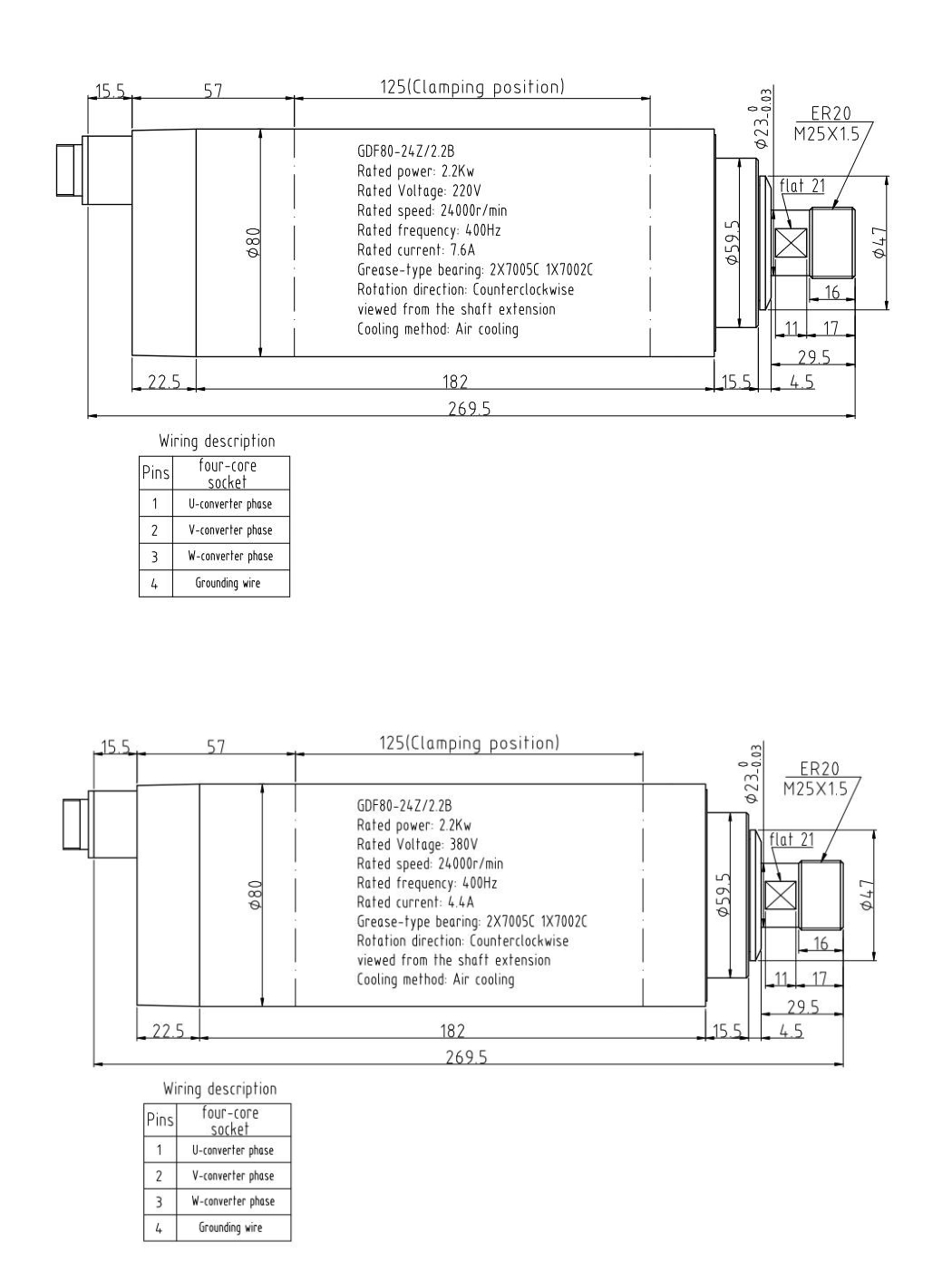
Locate the 125 mm clamp region on the drawing

The verified body diameter is 80 mm, overall assembly 269.5 mm and clamp region 125 mm. Use the exact installation drawing to locate the permitted support surfaces and nose references. The full assembly length is not available clamp length. Compare bracket geometry, nose datum and tool projection with the machine rather than treating the body diameter as the complete mounting interface.

Review rear clearance, cable routing, cooling access and relevant axis travel in the mounted position. The non-B GDF80 lists another overall length and tooling nose, while GDF46 Base Mount and Housing Mount use different support architecture. Include both exact drawings in a replacement discussion so the comparison locates the actual support and nose in the machine's envelope.

Keep the clamp and enclosure compatible with air cooling

Air cooling is the documented method. Review the supplied-unit cooling arrangement with the clamp position, guards and enclosure. Preserve the applicable air path and service access. The 2.2 kW rating does not establish a universal clearance or thermal setting, so provide working duty and any confined installation details that could limit cooling.

Check the relevant openings against brackets and nearby equipment, using the applicable service instructions and working environment. Converting an existing water-cooled installation requires a review of the new architecture rather than only removal of hoses. Route the motor cable while retaining access to support, cooling and tooling areas so both installation and maintenance can use the appropriate spaces.

INSTALLATION CHECKS

Match the whole assembly.

Use the drawing for this exact configuration to check mounting, clearances and connection locations.

  • Allow unobstructed cooling airflow and confirm any fan wiring.
  • Match the drive to the selected winding’s voltage and current.
Read the installation guide →
GDF80-24Z/2.2B dimensions and specifications drawing
Installation drawing · winding labels: 220 V / 7.6 A; 380 V / 4.4 A. Match the block or PDF for the winding you intend to order. View the drawing at full size.

Evaluate ER20 and support alongside the actual cycle

GDF80-24Z/2.2B is a candidate when manual ER20 tooling, air cooling and the documented operating point fit the process, and the machine accommodates its 80 mm body and clamp region. Begin with cutter and working speed, then review winding, drive, support and airflow. The GDF46 comparisons offer another mounting and operating-point choice rather than a universal upgrade path.

For engraving or milling, provide material, cutter geometry, shank diameter, projection, load cycle and machine stiffness. Those conditions support a suitability assessment. The motor and outline figures alone do not promise feed rate or finish. Include enclosure and bracket details where they constrain installation so the assessment considers the actual support and cooling as well as the tooling requirement.
Preserve the suffix, clamp region and nose datum

Send the current code, nameplate, support drawing and clear nose and connection photos. Compare the 80 mm body, 125 mm support region, 269.5 mm assembly and nose datum, followed by ER20 hardware, winding, drive output and airflow. A matching 2.2 kW rating or ER20 family narrows the comparison but leaves support and electrical applicability unresolved.

The GDF46/2.2 Base Mount and Housing Mount alternatives share ER20 but change rated speed and support architecture. GDF46/1.5 Base Mount also changes output and winding currents. Treat these as comparison candidates rather than approved substitutes. For an older unit, request current availability and retain the complete checklist when a successor is proposed, including exact drawing and supplied-winding evidence.

COMPARE RELATED SPINDLES

Compare the installation differences.

These models illustrate different interfaces and installation requirements. Check each drawing before choosing.

Swipe or scroll across to see all columns.

Use the left and right arrow keys to scroll this table.

ModelPower / dutySpeedInterfaceCoolingKey difference
GDF80-24Z/2.2BCurrent configuration2.2 kW rated24,000 rpm ratedER20Air-cooledØ80 mm · 269.5 mm overall · 125 mm clamp
GDF46-18Z/2.2 Base mount2.2 kW rated18,000 rpm ratedER20Air-cooledBase mount · 288.5 mm overall

GDF46/2.2 Base Mount retains ER20 but uses base fixing and an 18,000 rpm / 300 Hz point with a 288.5 mm assembly. Compare its actual support and 220 V current with this 80 mm body and 24,000 rpm / 400 Hz model.

GDF46-18Z/2.2 Housing Mount2.2 kW rated18,000 rpm ratedER20Air-cooledHousing Mount · 288.5 mm overall

GDF46/2.2 Housing Mount retains ER20 but changes support architecture and the rated point to 18,000 rpm / 300 Hz. Compare the housing drawing and 288.5 mm envelope with this 269.5 mm assembly and 125 mm clamp region.

GDF46-18Z/1.5 Base Mount1.5 kW rated18,000 rpm ratedER20Air-cooledBase Mount · 258.5 mm overall

GDF46/1.5 Base Mount uses ER20 at 18,000 rpm with lower rated output and different winding pairs, plus a 258.5 mm assembly. Compare base fixing and the working requirement with this 2.2 kW body-clamped model.

Put the B suffix and ER20 configuration in the request

Request GDF80-24Z/2.2B with 220 V / 7.6 A or 380 V / 4.4 A, quantity and destination country with postal code. List collets, nut, accessories and additional files required. Include the current bracket and drive information for replacement. A request for “GDF80 2.2 kW” leaves this ER20 model and the non-B ER16 version unclear.

Compare quotations for the same complete model, winding and included scope. Confirm accessory applicability and outstanding support or cooling issues before finalizing the machine installation. CINKR confirms proposed configuration and current availability by email. Retain the B-suffix drawing and selected winding information with the quotation so purchasing and installation refer to the same 125 mm-support assembly.

  • Winding: 220 V / 7.6 A or 380 V / 4.4 A
  • Configuration: GDF80-24Z/2.2B
  • Quantity, destination country and postal code
  • Required tooling, accessories and technical documents
Request a Quote

Use the B-suffix drawing and request applicable extra files

Open the full-size installation drawing below to review the 125 mm support region, nose geometry and connection layout. Request additional PDF, CAD or wiring information by complete B-suffix model and selected winding. A PDF labeled for the non-B GDF80 or a GDF46 Base Mount assembly does not establish applicability to this configuration merely because some motor figures match.

Confirm extra documents against the exact model before using them to locate support or set motor parameters. The outline, supplied-unit nameplate and service instructions address different questions, while the drive and machine procedures guide commissioning. State the unresolved mounting, cooling or electrical issue when requesting another file so the technical response can address the actual installation requirement.

DOWNLOADS

Files for this configuration.

View the installation drawing for dimensions and connections. Ask CINKR for any additional documents you need.

For CAD or additional installation drawings, include the exact model and configuration in your inquiry.

MODEL QUESTIONS

Questions about GDF80-24Z/2.2B

What tooling does the B-suffix configuration use?

This model uses manual ER20. The non-B GDF80-24Z/2.2 uses ER16, so retain the suffix in drawing and quotation requests.

Which winding pairs are listed?

Select 220 V / 7.6 A or 380 V / 4.4 A as a complete supplied configuration and keep it with the model during the VFD check.

What is the documented clamp length?

The clamp region is 125 mm. Use its location on the exact drawing rather than treating the 269.5 mm assembly as available support.

Does shared ER20 tooling establish a GDF46 replacement match?

Compare the actual support architecture, rated point, nose position, assembly space, winding and airflow. Shared tooling alone does not establish a replacement match.

Can another 2.2 kW GDF PDF be used without checking applicability?

Keep each file with its stated model, mounting and winding. Request applicable B-suffix documentation when needed.

What should a quotation request include?

Send the complete B-suffix model, winding, quantity, destination, accessories and document needs. Add nameplate, mount, nose, connection and drive evidence for replacement.

REQUEST A QUOTE

Request a quote for GDF80-24Z/2.2B

Include the winding, quantity and installation details for this configuration. Unknown technical details can be left blank.

Useful details to have ready
  • Exact code and readable nameplate
  • Mounting dimensions and available clearance
  • Tool interface and required speed
  • Drive output, cooling and ATC connections

Attach photographs or drawings in your email application.

Machine and technical details (optional)
Review your inquiry
Include your spindle model, machine requirements and questions in your email.
Open email

Open your email application to review and send the inquiry, or copy the text into a message to info@cinkr.com. Quotes and availability are confirmed by email.

Open original image

Zoom to read details. Scroll horizontally or vertically to move around the image.

GDF80-24Z/2.2B product photo
Open original image

Zoom to read details. Scroll horizontally or vertically to move around the image.

GDF80-24Z/2.2B installation drawing