GDK100-12-24Z/2.2-4.4 spindle

GDK SERIES · MANUAL

HQD GDK100-12-24Z/2.2-4.4 ER20 spindle motor

2.2 kW ratedER20Water-cooled12,000–24,000 rpmØ100 mm295 mm overall

HQD GDK100-12-24Z/2.2-4.4 is a water-cooled ER20 spindle with a documented 12,000–24,000 rpm operating range and 2.2 kW rated output. The separate power curve includes a higher 4.4 kW line under its stated duty conditions. Check the U/f relationship, 100 mm body and 140 mm clamp region before comparing it with a fixed-speed-point GDK.

Browse the GDK spindle range →

MODEL SELECTION

Is this the right GDK100-12-24Z/2.2-4.4 configuration?

BEST FIT

Choose this configuration if:

  • The process needs the documented 12,000–24,000 rpm range and can be checked against the actual power curve and duty.
  • The machine uses manual ER20 tooling and can support the 100 mm body over the 140 mm clamp region.
  • Water cooling and a drive capable of the 400–800 Hz U/f relationship can be integrated.

CHECK BEFORE ORDERING

Confirm these details first:

  • Keep 2.2 kW rated separate from the 4.4 kW curve level and S1/S6-20%, TA20°C conditions.
  • 269–380 V describes the curve relationship, not selectable 269 V and 380 V windings or a mains supply range.
  • Check the 295 mm assembly, nose and collet-nut clearance, cooling connections and any air-seal requirement.

COMPARE ALTERNATIVES

Consider another model when:

  • GDK105-9-21Z/2.2-5.0 begins at 9,000 rpm and changes the body and assembly dimensions.
  • GDK100-24Z/3.2 lists a 24,000 rpm point and separate winding pairs; GDK85-24Z/2.2D changes the body to 85 mm.
Selection and installation topics

SPECIFICATIONS

Read the operating conditions.

The rated output is 2.2 kW. The drawing lists 6.8 A, 12 kg, a 100 mm body and 295 mm overall length. Additional power on the curve depends on the stated duty conditions.

Swipe or scroll across to see all columns.

Use the left and right arrow keys to scroll this table.

Output and duty
Rated power (kW)2.2
Operating range (rpm)12,000–24,000
Tooling and mounting
Tool interfaceER20
Tool changeManual tool change
Electrical
Rated current (A)6.8
Frequency range (Hz)400–800
Curve voltage endpoints (V)269–380
Dimensions and weight
Body diameter (mm)100
Overall length (mm)295
Clamping length (mm)140
Weight (kg)12
Cooling and feedback
CoolingWater-cooled

Power curve: S1 and S6-20% at TA20°C are distinct duty conditions. The 2.2–4.4 model code and 269–380 V curve endpoints do not establish continuous 4.4 kW output or separate winding options.

2.2 kW rated and the separate duty-conditioned curve

The outline drawing identifies 2.2 kW rated output for this configuration. Its operating range is 12,000–24,000 rpm, with 400–800 Hz frequency information. The power and torque graph separately shows 2.2 kW and 4.4 kW lines and carries S1/S6-20%, TA20°C and water-cooling notes. Keep the graph and its conditions together. The larger number in the model code is not an unconditional continuous rating or evidence of a second freely selectable spindle.

Describe the actual working-speed range and load cycle before selecting the spindle. A process that needs sustained output and one that needs a different intermittent load pattern require the applicable curve and duty information to be considered. Do not compare this model as a bare “4.4 kW spindle” against a continuous rating on another model. If a particular output is required at a particular speed, identify that working point and ask for the supplied configuration to be checked against it.

Read 269–380 V as a U/f relationship

The voltage curve shows 269 V at 400 Hz / 12,000 rpm and 380 V at 800 Hz / 24,000 rpm. Those endpoints describe the identified operating relationship. They are not two winding choices and do not establish that the spindle can be connected directly to any mains voltage between them. The listed current is 6.8 A. Compare the complete curve and motor information with the drive's output capability rather than choosing voltage from one printed endpoint.

Check output frequency, voltage behavior, current capability and the motor information required by the VFD's setup procedure. The drive's input supply is a separate requirement. Include the drive model and output specifications if it is already installed, together with the intended working speeds and duty. A matching nominal kW designation is insufficient if the drive cannot support the required high-frequency output or appropriate operating relationship.

No separate selectable winding pairs are listed for this curve configuration. If an alternative electrical supply is required, request confirmation of the proposed motor and drive arrangement instead of borrowing the 220 V / 380 V choices from GDK100-24Z/3.2. Use the supplied-unit label, applicable curve and drive instructions before setting motor data. Keep the full “12-24Z/2.2-4.4” code with those documents so the fixed-point GDK100 is not mixed into the review.

Manual ER20 tooling and the spindle nose

This GDK uses manual ER20 collet tooling. Match the tool shank to the particular collet's marked gripping range and review the collet, nut and spindle nose as an assembly. ER20 is not a single tool-shank diameter and does not establish every nut thread or clearance dimension. Check the nose drawing and supplied tooling details before purchasing accessories or assuming that a nut from another ER20 spindle will fit.

The tool is changed manually; this configuration does not provide the ISO or BT taper and release system of a GDL ATC spindle. If automatic tool change is required, select from the appropriate tooling architecture and review the complete control and pneumatic installation. For this manual configuration, the practical installation check includes wrench access, nut clearance and the holder/tool projection needed by the machine. Keep those mechanical requirements alongside the working-speed and drive review.

100 mm body with a 140 mm clamp region

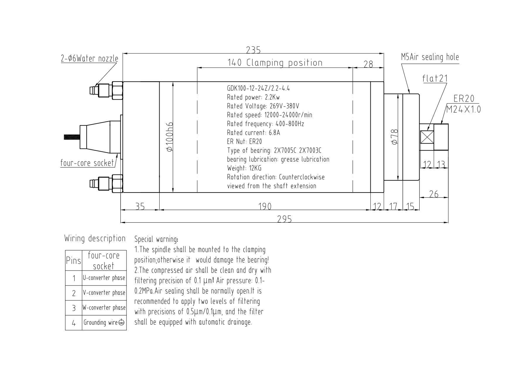
The verified dimensions are 100 mm body diameter, 140 mm clamping length and 295 mm overall length, with a 12 kg listed weight. Check each from its drawing reference. The diameter concerns the clamp fit, the support region concerns how the spindle is held, and the overall length concerns nose and rear clearance. Do not treat the complete length as available support or infer the nose position only from the end-to-end dimension.

Compare the machine mount with the labeled support region and connection locations. Review collet-nut and wrench access, intended tool projection, rear fittings and service routing throughout the relevant axis travel. GDK100-24Z/3.2 shares several broad dimensions, but the shared body size does not resolve nose hardware, electrical setup or the required operating curve. A replacement review should therefore retain both exact model codes and drawings even when the initial dimensional comparison looks promising.

Water cooling and front-end service checks

This configuration is water cooled, and the power curve explicitly carries that condition. Confirm the supplied spindle's cooling connections and requirements with the proposed circuit and actual production duty. The 2.2 kW rated value or higher curve line does not specify a universal coolant flow, temperature or pump setting. Include existing cooling equipment details so the technical discussion can check the complete arrangement.

Review any front air-seal connection and its supplied-unit requirements from the exact drawing and instructions. Do not transfer a pressure value from another GDK when it is not established for this configuration. Air sealing and water cooling answer different installation questions; one does not replace the other. Route services with access for fitting, inspection and machine movement, and include connection photos if an existing circuit or mount will be reused.

INSTALLATION CHECKS

Match the whole assembly.

Use the drawing for this exact configuration to check mounting, clearances and connection locations.

  • The higher curve output is duty-dependent; do not use it as continuous rated power.
  • Curve voltage endpoints do not establish selectable winding configurations. Also check the air-sealing connection shown in the drawing.
  • Use the dimensional PDF and original power curve for installation checks.
Read the installation guide →
GDK100-12-24Z/2.2-4.4 dimensions and specifications drawing
Installation drawing. View the drawing at full size. Choose the PDF labeled for your configuration below.

Select for a working range, not the larger code number

Evaluate this model when the process requires manual ER20 tooling, water cooling and the documented 12,000–24,000 rpm range. Compare the actual operation with the curve and duty description, then check drive output and mounting. GDK105's 9,000–21,000 rpm range is a useful comparison when a lower starting point matters, but its different body, complete length and curve must be assessed independently.

For engraving or milling, include the material, cutter geometry, shank size, normal working speeds, load cycle and machine stiffness. These inputs support a conditional selection discussion rather than a guaranteed machining result. A model-code power range alone cannot establish feed rate, surface finish or material-removal capacity. If the planned working point depends on the higher curve level, resolve its applicable duty and cooling requirements before accepting the spindle for the process.

Shared 100 mm dimensions do not settle the drive review

Provide the current spindle's full code, readable label, mounting drawing and nose and connection photos. Compare body, support region, nose datum, total assembly and tooling hardware, then review the operating range, U/f relationship, drive output and cooling. Keep any air-seal requirement explicit. A matching 100 mm body or ER20 designation does not establish identical electrical behavior or acceptable output for the intended duty.

The fixed-point GDK100-24Z/3.2 has a different electrical description with separate winding pairs. GDK105-9-21Z/2.2-5.0 changes the working range and body, while GDK85-24Z/2.2D uses an 85 mm body. The comparison reasons below identify which requirement would change. They are not accepted replacement conclusions. Ask for current availability for an older installation and check any proposed successor against the same complete mechanical and electrical evidence.

COMPARE RELATED SPINDLES

Compare the installation differences.

These models illustrate different interfaces and installation requirements. Check each drawing before choosing.

Swipe or scroll across to see all columns.

Use the left and right arrow keys to scroll this table.

ModelPower / dutySpeedInterfaceCoolingKey difference
GDK100-12-24Z/2.2-4.4Current configuration2.2 kW rated12,000–24,000 rpmER20Water-cooledØ100 mm · 295 mm overall · 140 mm clamp
GDK105-9-21Z/2.2-5.02.2 kW rated9,000–21,000 rpmER20Water-cooledØ105 mm · 344 mm overall · 155 mm clamp

Compare a 9,000–21,000 rpm range in a 105 mm body and 344 mm assembly with this 12,000–24,000 rpm, 100 mm configuration.

GDK100-24Z/3.23.2 kW rated24,000 rpm ratedER20Water-cooledØ100 mm · 295 mm overall · 140 mm clamp

Compare a 3.2 kW, 24,000 rpm point at 400 Hz with separate winding pairs against this 2.2 kW rated range model and its U/f relationship.

GDK85-24Z/2.2D2.2 kW rated24,000 rpm ratedER20Water-cooledØ85 mm · 284 mm overall · 125 mm clamp

Compare 2.2 kW at 24,000 rpm in an 85 mm body and 284 mm assembly; body size and electrical description differ from this range configuration.

Quote the exact range configuration and intended duty

Include GDK100-12-24Z/2.2-4.4, quantity, destination country and postal code. Describe the working speeds, load cycle and existing drive, and list required collets, accessories or additional documents. Do not request a “269 V winding” from the curve endpoint. If another electrical arrangement is needed, state it as a requirement to be confirmed with the exact motor and drive proposal.

When comparing quotations, check that each covers the same range configuration, tooling, documents and supply scope. A price labeled only “GDK100 4.4 kW” leaves the rated/duty distinction unresolved. CINKR confirms configuration and current availability by email. Keep the agreed outline drawing and operating curve with the quotation so purchasing and installation share the same model, electrical relationship and duty context.

  • Winding: confirm the supplied-unit electrical specification
  • Configuration: GDK100-12-24Z/2.2-4.4
  • Quantity, destination country and postal code
  • Required tooling, accessories and technical documents
Request a Quote

The outline and curve PDF answer different questions

Two identified files are offered below: the outline drawing and the voltage, power and torque graph. Use the outline for the rated specification block, clamp region and dimensions. Use the graph for the U/f relationship and separate power lines with S1/S6-20%, TA20°C and water-cooling conditions. Retain both applicability labels when comparing the spindle with the machine and drive.

Open the full-size installation drawing to inspect mounting and connection details. Request any additional CAD or supplied-unit connection document by the exact range model. A file for GDK100-24Z/3.2 must not be substituted because the body looks similar. Confirm an additional document's applicability before using it to finalize motor parameters, accessories or the machine installation.

DOWNLOADS

Files for this configuration.

PDF · 161 KB

Dimensions, specifications and wiring

GDK100-12-24Z/2.2-4.4 · 2.2 kW rated; 269–380 V U/f relationship

English

Download PDF

PDF · 146 KB

Voltage, power and torque curves

GDK100-12-24Z/2.2-4.4 · S1/S6-20%, TA 20°C; 269–380 V U/f relationship

English

Download PDF

For CAD or additional installation drawings, include the exact model and configuration in your inquiry.

MODEL QUESTIONS

Questions about GDK100-12-24Z/2.2-4.4

Is 4.4 kW the continuous rated output?

The outline drawing identifies 2.2 kW rated. The separate graph has a 4.4 kW line with S1/S6-20%, TA20°C and water-cooling notes; retain those conditions instead of claiming unconditional continuous 4.4 kW.

Can I choose a 269 V winding?

269–380 V describes the U/f curve relationship. It is not a list of independently selectable windings or the VFD's mains input range.

What drive frequency range is listed?

The documented operating range is 12,000–24,000 rpm with 400–800 Hz information. Check the complete curve, current and output-voltage behavior with the proposed VFD.

Does the ER20 interface confirm the nut thread?

ER20 identifies the collet family. Check the supplied nose, nut and collet details; it does not establish every thread or accessory dimension.

Can it replace GDK100-24Z/3.2 based on size?

Both list a 100 mm body, but their operating and electrical descriptions differ. Compare exact drawings, nose hardware, duty, drive output and cooling before deciding.

Which documents should stay with the quote?

Retain the identified outline drawing and curve PDF with the exact model, intended duty and drive information. Include quantity, destination and required accessories in the inquiry.

REQUEST A QUOTE

Request a quote for GDK100-12-24Z/2.2-4.4

Include the winding, quantity and installation details for this configuration. Unknown technical details can be left blank.

Useful details to have ready
  • Exact code and readable nameplate
  • Mounting dimensions and available clearance
  • Tool interface and required speed
  • Drive output, cooling and ATC connections

Attach photographs or drawings in your email application.

Machine and technical details (optional)
Review your inquiry
Include your spindle model, machine requirements and questions in your email.
Open email

Open your email application to review and send the inquiry, or copy the text into a message to info@cinkr.com. Quotes and availability are confirmed by email.

Open original image

Zoom to read details. Scroll horizontally or vertically to move around the image.

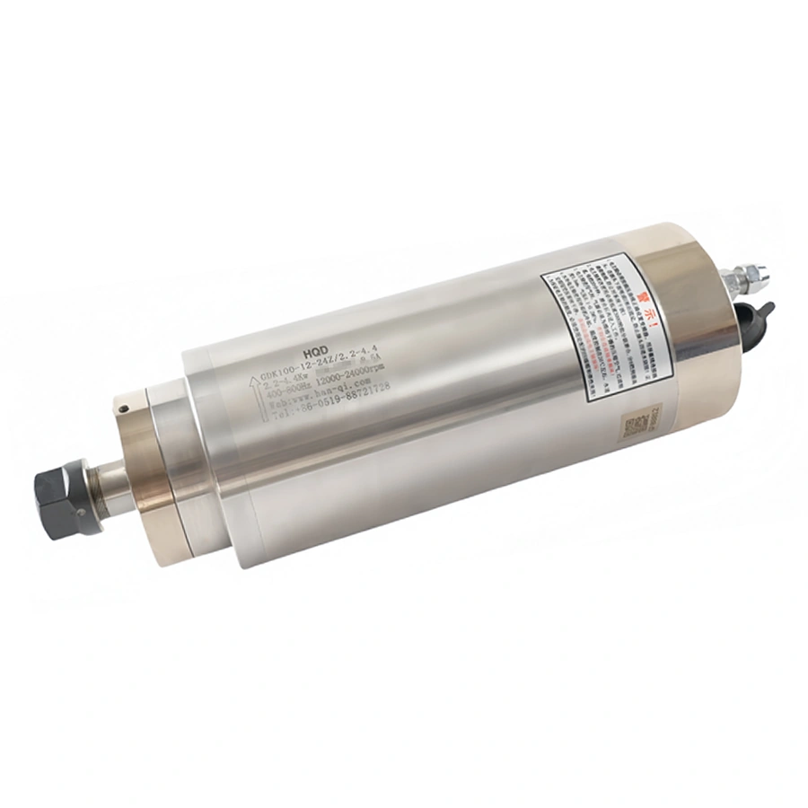
GDK100-12-24Z/2.2-4.4 product photo
Open original image

Zoom to read details. Scroll horizontally or vertically to move around the image.

GDK100-12-24Z/2.2-4.4 installation drawing