Key Requirements and Configuration Checks
- Separate thin sheet, extrusion walls and block roughing.
- Check cutter projection, fixture support and chip removal.
- Use the actual operating curve instead of extrapolating rated power.
Match the proposed configuration to its applicable drawing, operating data and machine requirements. Resolve mounting dimensions, auxiliary services and operating limits before accepting a spindle for the intended installation.
| Task | Process question | Evidence |
|---|---|---|
| Sheet profiles | Is the panel supported as the perimeter is cut? | Hold-down, toolpath and cutter data |
| Extrusion features | Can the wall and fixture resist the operation? | Cross-section, clamping and tool projection |
| Spindle shortlist | Does the working point fit tooling and drive? | Spindle curve, supplied winding and VFD data |
Identify the aluminum task before choosing the motor
Aluminum sheet profiling, machining an extrusion wall and roughing a solid block are different tasks. Specify the material identification, thickness or cross-section, feature and surface requirement. Keep the stock condition in the job record. A general label such as aluminum machining does not describe how much of the cutter is engaged or how the workpiece will be supported.
For sheet work, inspect what happens when the perimeter cut releases the part. The remaining material, tabs or fixture must keep the part controlled through the toolpath. For extrusions, thin walls and internal cavities can complicate support and tool access. Check the cross-section and the planned clamping locations before interpreting vibration or edge damage as a spindle-power problem.
Sheet profiles, extrusion features and lightweight aluminum parts require a CNC router whose structure, motion system, spindle and workholding support the intended operation. Solid-block roughing can introduce substantially different engagement, access and support requirements, so it needs a separate capability review. Provide the part geometry, stock, fixture and removal strategy to the machine builder before extending an established sheet-cutting process. A spindle's kW rating does not establish that the router has the rigidity, travel, feed control or chip-handling capability required for block machining.
Choose tooling and projection for the operation
Obtain the cutter manufacturer's recommendations for the actual material, operation and engagement. Cutting-edge diameter, flute geometry, number of edges and tool projection all belong in the selection. Do not reduce the task to a universal rule that aluminum always needs one flute or one spindle speed. Tooling suppliers provide different products for sheet cutting, slotting, roughing and finishing.
Match the actual tool shank to a compatible individual collet or holder and retain the assembly's permitted operating conditions. A 1/4-inch shank is 6.35 mm and must remain distinct from a 6 mm tool in the inventory. Record each cutter's shank, collet family and size, matched nut or holder, projection and maximum permitted speed. A larger ER family provides additional shank options, but does not correct a damaged clamp, establish suitable runout or increase the stiffness of a long cutter. Inspect the actual assembly and its support before changing the spindle configuration.
Use the shortest suitable projection that meets the feature and follows the tooling instructions. More reach changes how the tool and holder behave under load, so it needs a process review. If the fixture forces excessive extension, consider the workholding and access arrangement with the machine and tooling suppliers. Additional rated spindle power cannot remove deflection caused by an unsuitable tool or unsupported workpiece.
Check the relationship between speed and feed
For a feed calculation, feed in mm/min equals spindle RPM multiplied by cutting edges multiplied by chip load in mm per tooth. The equation is useful only when its inputs belong to the actual tool and operating condition. Use the cutter data for engagement and material, then confirm that the machine can deliver the feed on the intended path.
For illustration, assume a one-edge tool and a hypothetical 0.04 mm chip load at 18,000 rpm. The arithmetic feed is 720 mm/min. A two-edge tool with the same assumed chip load and RPM gives 1,440 mm/min. These are calculation examples, not aluminum cutting recommendations. Neither value establishes whether an HQD model, a particular router or a cutter can perform the job.
Actual feed can fall below the commanded value on corners and short segments. Record the motion behavior instead of reading the programmed number as a constant. If a chosen tool requires conditions the machine cannot deliver, revise the process with the tooling supplier. Do not select 24,000 rpm simply because the spindle permits it, or reduce speed to an arbitrary value without reviewing the cutter and motor operating limits.
Put chip removal in the process check
Fresh chips need a path away from the cutting zone. A confined slot, a deep feature or an extrusion cavity can make removal more difficult than an open profile cut. Chips that remain in the path can be cut again, so inspect evacuation alongside the cutter and engagement. Confirm the machine's permitted lubrication and chip-handling arrangement for the actual job.
If material begins adhering to a tool, stop the trial according to the machine procedure and inspect the tool and process conditions before continuing. Record stock, cutter, projection, speed, feed, engagement and removal method. Repeating the same cut with a larger motor is not a diagnosis. Ask the tool supplier to evaluate the geometry and conditions when the evidence does not identify a clear cause.
Keep spindle cooling separate from cutting-zone cooling or lubrication. A water-cooled motor has a circuit serving the spindle; that label does not mean it supplies cutting fluid to the workpiece. Similarly, pneumatic functions at an ATC assembly can serve release, sealing or cleaning. Follow the exact connection documentation instead of treating all services as interchangeable ways to clear chips.
Evaluate support and machine stiffness
Thin sheet and extrusion walls need a holding plan appropriate to the operation. Describe the clamping or vacuum arrangement, unsupported spans and how support changes as material is removed. The spindle cannot compensate for a part that moves at the final pass. For long extrusions, consider where the feature sits relative to the clamp and whether the wall is supported near the cut.
| Observation during a trial | Check before changing spindle power | Evidence to record |
|---|---|---|
| Vibration or changing finish | Tool projection, fixture support, assembly and engagement | Location, cutter, holding and process conditions |
| Material adhering to the cutter | Tool suitability and chip/lubrication conditions | Stock, speed, feed, tool condition and removal method |
| Part moves near the final cut | Remaining support and hold-down sequence | Toolpath stage, fixture and remaining stock |
| Drive trips or motor speed changes | Exact fault, drive match and process load | Fault code, working point and winding data |
Use a controlled comparison when evaluating a change. Change one condition at a time where the trial procedure allows it, and keep the other conditions recorded. This avoids attributing an improvement to spindle power when the replacement trial also changed the tool, fixture and engagement. Have the machine supplier approve trials that approach its stated operating limits.
Compare HQD operating points rather than headline numbers
Compare the required tool interface, working speed, machine support and installation services before selecting a spindle for aluminum. GDZ, GDK and GDL configurations differ in these conditions, and none of their headline ratings establishes a proven cutting process for the intended part. Match the candidate to the actual machine and cutter requirements, review its supplied operating curve and drive data, and define a representative trial with acceptance criteria for dimensions, finish and stable operation.
| Configuration | Documented output | Speed information | Interface | Mechanical comparison |
|---|---|---|---|---|
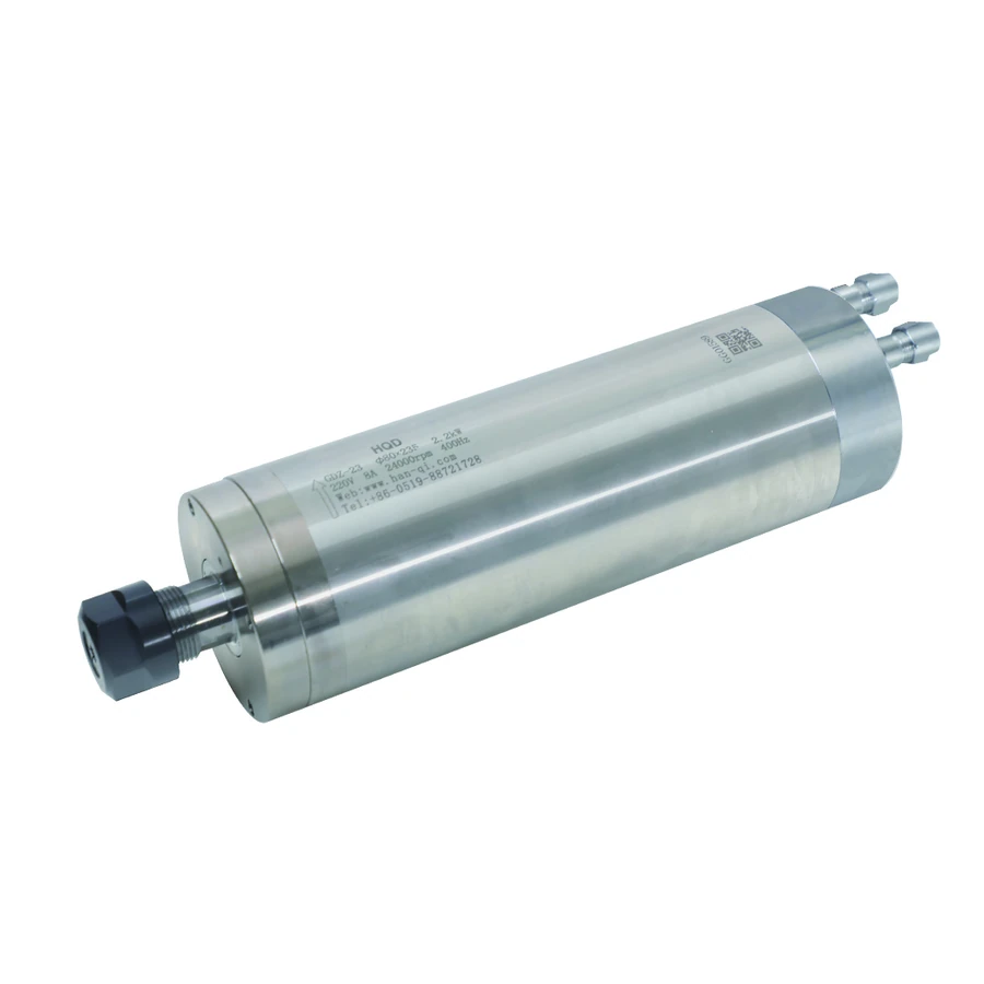
| GDZ-23 | 2.2 kW rated | 24,000 rpm rated | ER20 manual | 80 mm body; 6 kg |
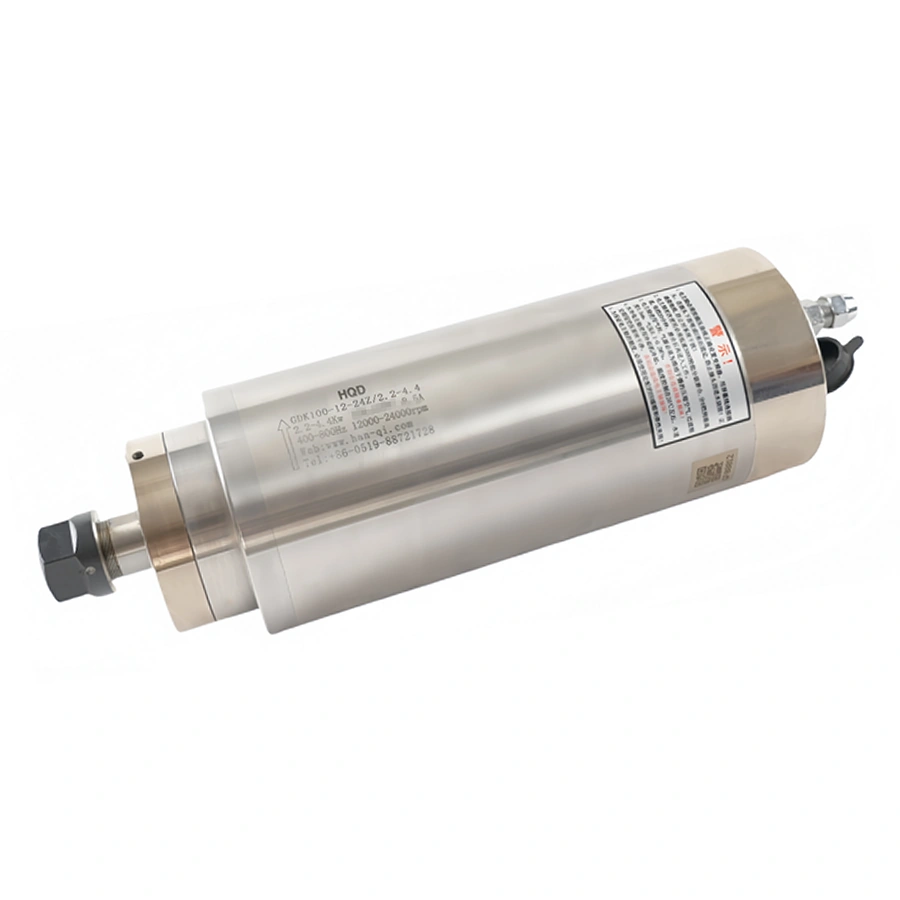
| GDK100-12-24Z/2.2-4.4 | 2.2 kW rated; higher curve values have conditions | 12,000–24,000 rpm | ER20 manual | 100 mm body; 12 kg |
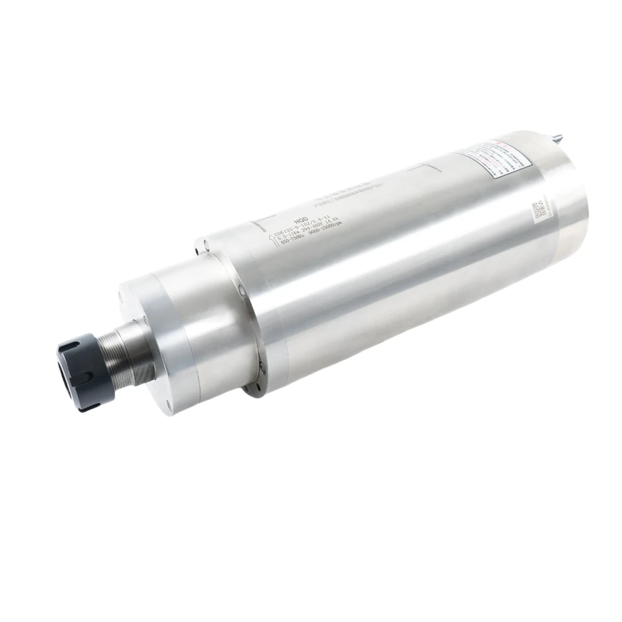
| GDK125-9-15Z/5.5-11 | 5.5 kW rated | 9,000–15,000 rpm | ER32 manual | 125 mm body; 31 kg |
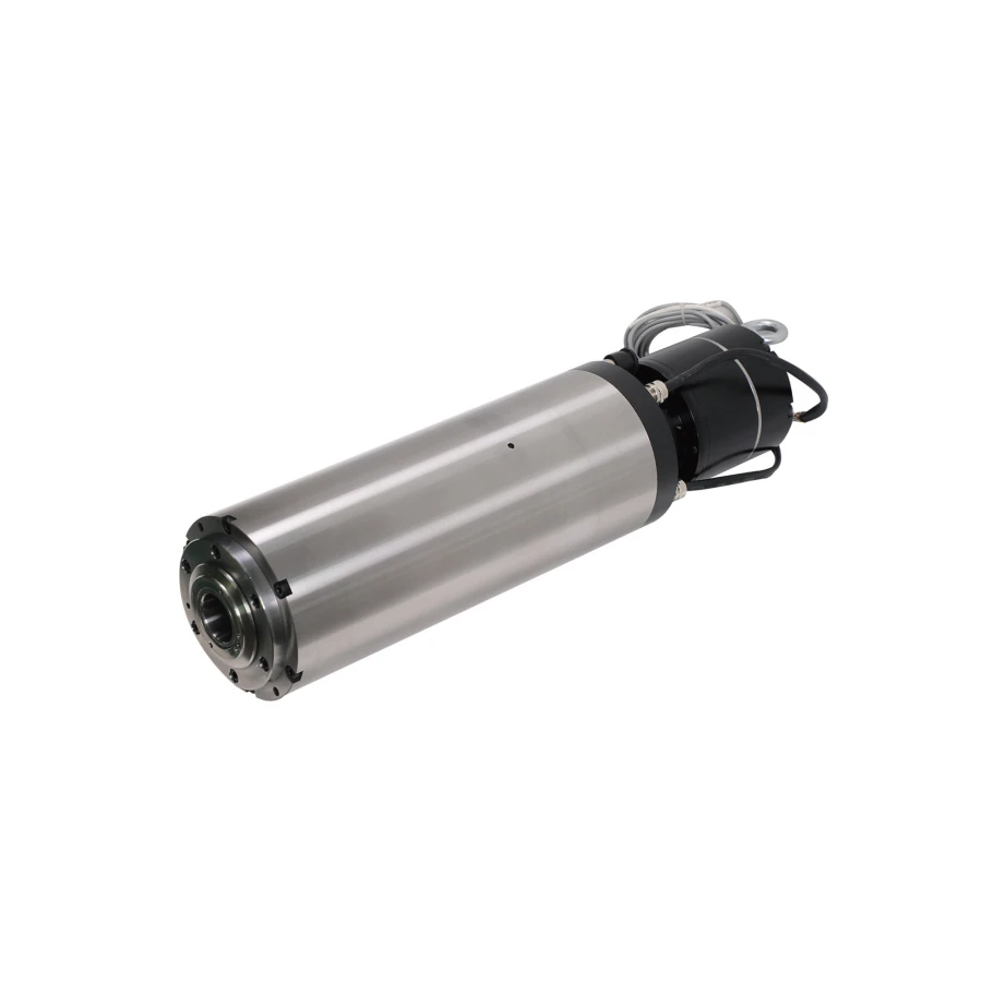
| GDL120-30-24Z/5.5 | 5.5 kW rated | 24,000 rpm rated | BT30 ATC | 120 mm body; 25 kg |
The larger GDK125 assembly changes the machine support question as well as the speed range. The BT30 example adds toolholder, rack and release-system checks. Neither is a direct answer to a problem on a compact ER20 installation. Compare the clamp area, nose and service envelope, machine mass allowance and complete tooling arrangement before moving beyond the shortlist.
Read torque and low-speed conditions correctly
A power rating at one speed does not establish the available power at every lower speed. Inspect the original power and torque curves and the operating limits for the supplied unit. A drive that can command a low frequency does not by itself establish that the spindle is approved for the desired loaded operation or cooling condition at that frequency.
GDK100-12-24Z/2.2-4.4 is documented over 12,000–24,000 rpm, with a voltage relationship from 269 V at 400 Hz to 380 V at 800 Hz. Those endpoints describe paired points on its operating curve rather than independently selectable windings. The 2.2 and 4.4 kW curves also retain S1/S6-20% and TA20°C conditions; the larger suffix does not establish continuous 4.4 kW output. Identify the power documented at the intended speed, retain the relevant duty and cooling requirements, and obtain the supplied motor's cycle instructions before evaluating the proposed aluminum operation.
For GDL120, retain the documented winding voltage and current as a matched pair, and verify that the VFD supports the required output voltage, current and frequency. Check the drive's input supply separately; an available workshop voltage does not establish the motor winding or the drive's high-frequency output capability. If the proposed operation requires a lower working speed than the available spindle evidence supports, obtain the supplied unit's curve and operating instructions before proceeding. A torque calculation is useful only when its power value is documented at that same speed and duty.
Define a useful trial and acceptance record
Choose a representative feature and material from the intended job. Have the machine and tooling suppliers establish suitable initial conditions, holding and trial limits. Document the accepted dimensions and finish requirement before starting; a visually smooth demonstration is not a complete acceptance test for the production part.
| Trial record | Information to retain |
|---|---|
| Material and feature | Identification, thickness, cross-section and operation |
| Tool and assembly | Supplier part, diameter, shank, edges, holder and projection |
| Machine and support | Machine model, mount, fixture and remaining stock support |
| Conditions | RPM, programmed and observed feed, engagement and chip removal |
| Spindle and drive | Full code, supplied winding, drive model and fault record |
| Result | Dimensions, finish, tool condition and any vibration or speed change |
| Next action | One proposed change with its reason and acceptance condition |
Repeat the accepted conditions before making a claim about sustained production. Check the working cycle and cooling against the supplied spindle documentation. Where information such as operating current is available from the machine, record it using the machine supplier's method and context. Do not treat an isolated current percentage as a complete measurement of spindle output or remaining cutting capacity.
Use finishing passes to separate geometry from output
An extrusion job may need both a dimensional feature and a clean edge. Record those acceptance requirements separately. Choose a representative feature that exposes the actual wall support and cutter reach rather than using an easy open edge as the sole demonstration. Retain stock identification and the cross-section drawing so the accepted trial can be compared with later production material.
For a proposed finishing operation, ask the tooling supplier to define a suitable tool and engagement for that feature. Keep the remaining stock and support condition in the record. If the result changes along the extrusion, compare clamping position, projection, part support and tool condition before interpreting the pattern as a lack of spindle power. The location of the defect can be useful evidence in that investigation.
Distinguish the result after machining from the result after unclamping, where the part requirement calls for both. Thin stock can be sensitive to how it is held, so define the inspection state in the acceptance plan. Use the machine and fixture suppliers' guidance for the intended part; a single nominal dimension recorded while clamped does not describe every required inspection condition.
Once an acceptable operation is established, save the tool assembly, fixture arrangement, stock and conditions as a controlled job record. A future change in cutter, spindle or fixture then has a meaningful baseline. This turns a spindle comparison into a repeatable procurement and production decision, rather than a general claim that one motor can machine aluminum.
Keep block roughing as a separate capability question
Solid blocks can involve different tool engagement and structural requirements from sheet profiles. Before extending a router process to block roughing, ask the machine builder to review the part, fixture, tool and removal strategy. Check travel, loading, chip handling and the machine's permitted operating conditions. A high-power spindle fitted to a machine does not reclassify the machine's capability.
Where a lower-speed operating point is required, use the documented spindle curve and exact tooling limits. Where tool changes are required, evaluate holder and rack integration. These choices should be made together with the machine structure and workholding, not ranked by spindle kW in isolation. If the job lies outside the machine's documented envelope, a different machine or process may be the practical choice.
Prepare the inquiry around a representative job, actual tool inventory, machine and fixture details, required working point and unresolved checks. For each candidate, record the tool interface, documented speed and duty, mount, mass, drive and cooling requirements. Distinguish a compact GDZ-23 installation from the heavier GDK options or a BT30 GDL120 project that also requires holder, rack and release integration. Define acceptance on the intended machine and process, and retain calculated examples separately from measured trial results so later tooling or stock changes can be assessed against a reliable baseline.